Input devices
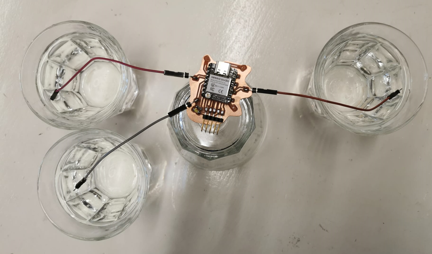
This week I want to make a board using ESP32 S3 and capacative touch to create water level sensors for my humidifier. I think I will need 6 of them.
Group assignment
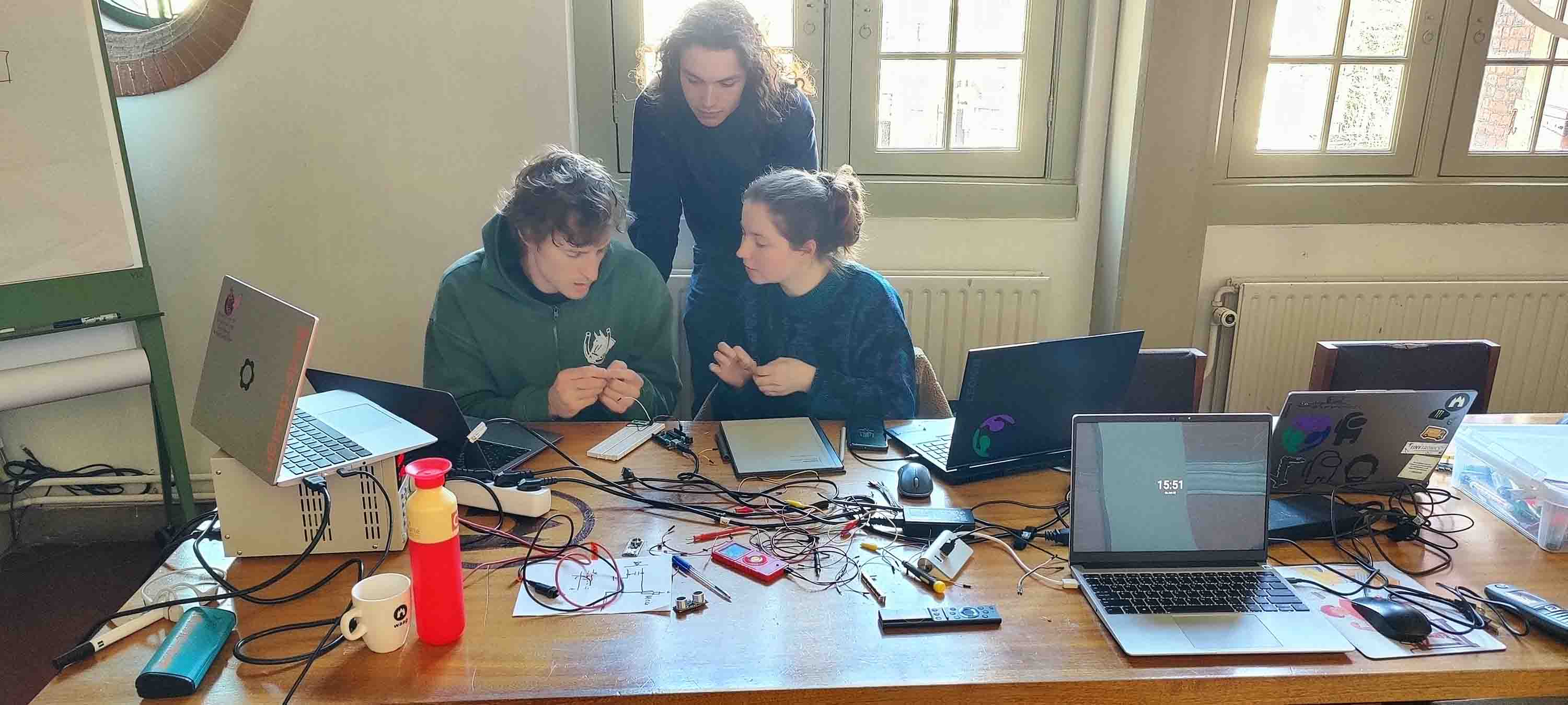
Oscilloscope and button
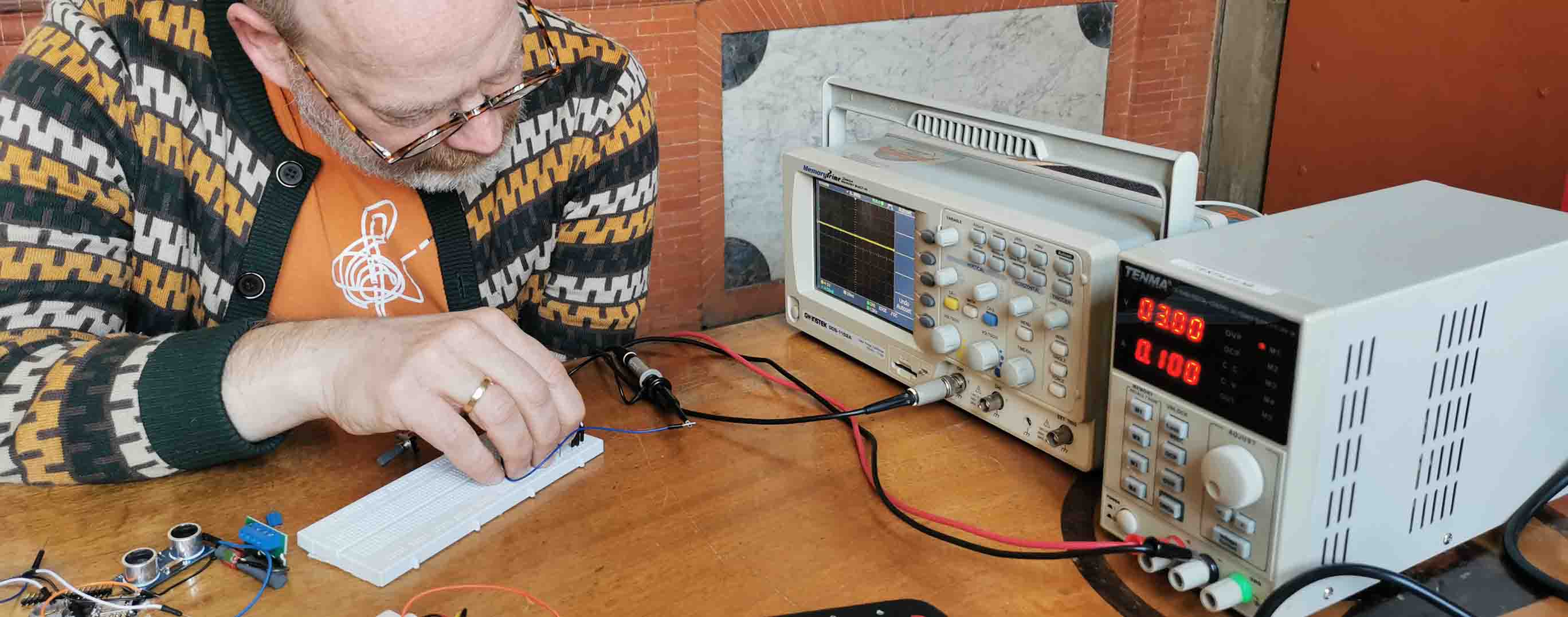
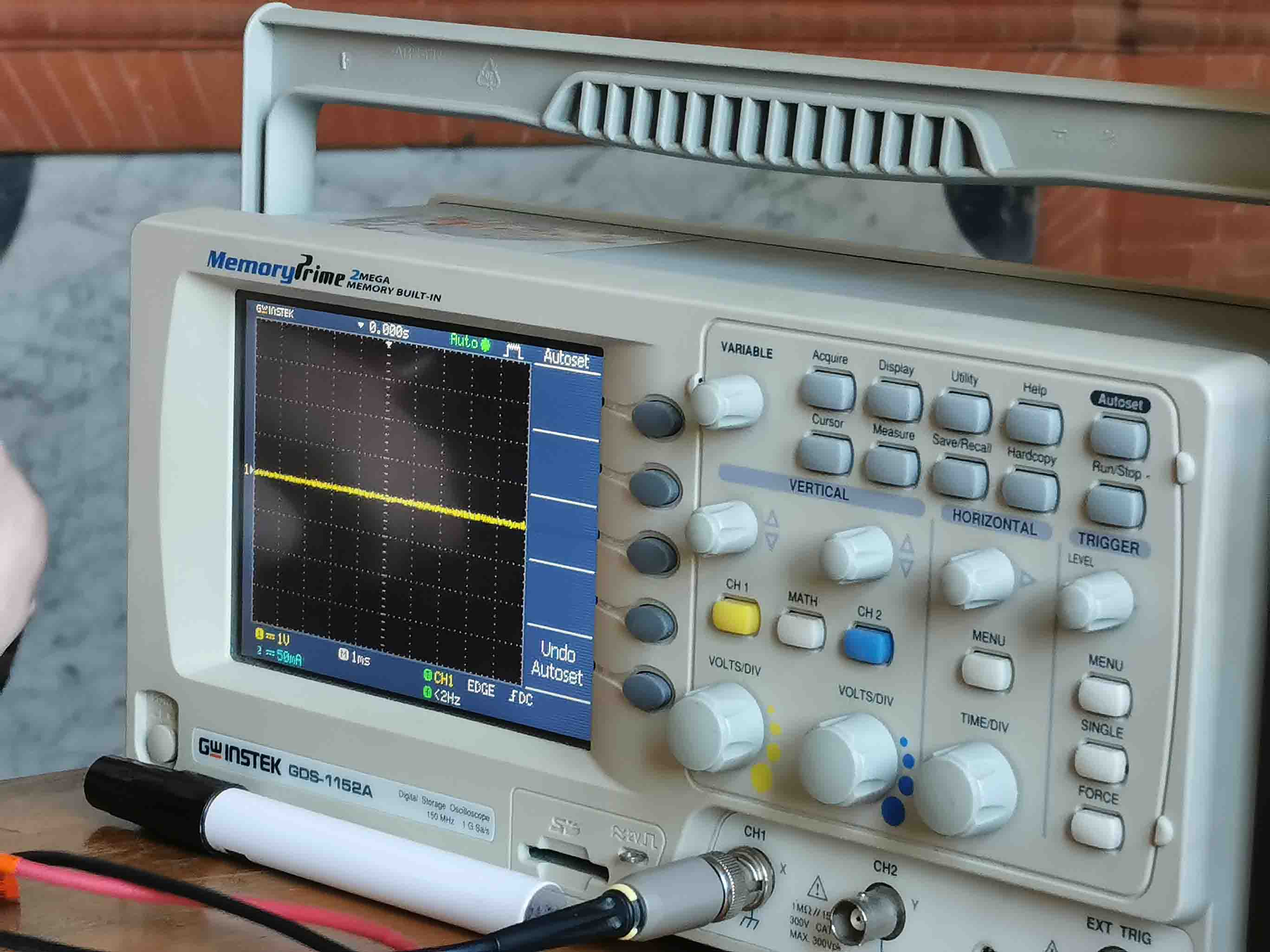
Using an oscilloscope to measure the resistance altered with a potentiometer in teh form of a slider. In teh 2 pictures below it is clear how moving the slider has changed the resistance.
Here the slider is on one side of the potentiometer:
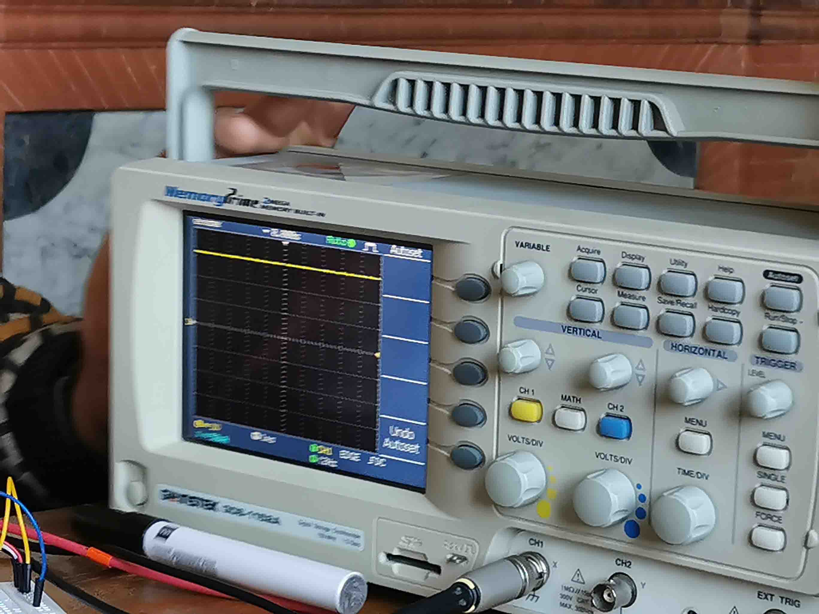
As it moves to teh other side the voltage goes down.
Here is the humidity sensor DHT22 hooked up to a logic analyser.

The logic analyser turned out to be no good for this kind of sensor. It can see that there is data being transferred but cannot tell which way it is being sent. This is because it is a 1 wire comminication.
DS18D20 temperature sensor
Next sensor up was a: ds18d20
When Henk first hooked it up to Arduino IDE it looked like this:

Erwin explained that this was a weird number and probably not a faulty reading but rather that the sensor was not measuring at all.
Then after adding a physical pullup resistor it looked like this: A much more realistic number:

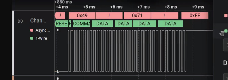
Here is the digital reading of the sensor using a logic analyser:

The sensor first resets and then gets a more stable reading.
On the left side we could see the data transfer.
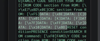
Here is the message in binary:

Movement sensor
We tried to hook up a movement senor. From reding the datasheet we saw that it should only need to be powered up to work. Using the reccomendations form the datasheet we hooked up an LED to see when it was detecting movement and not.
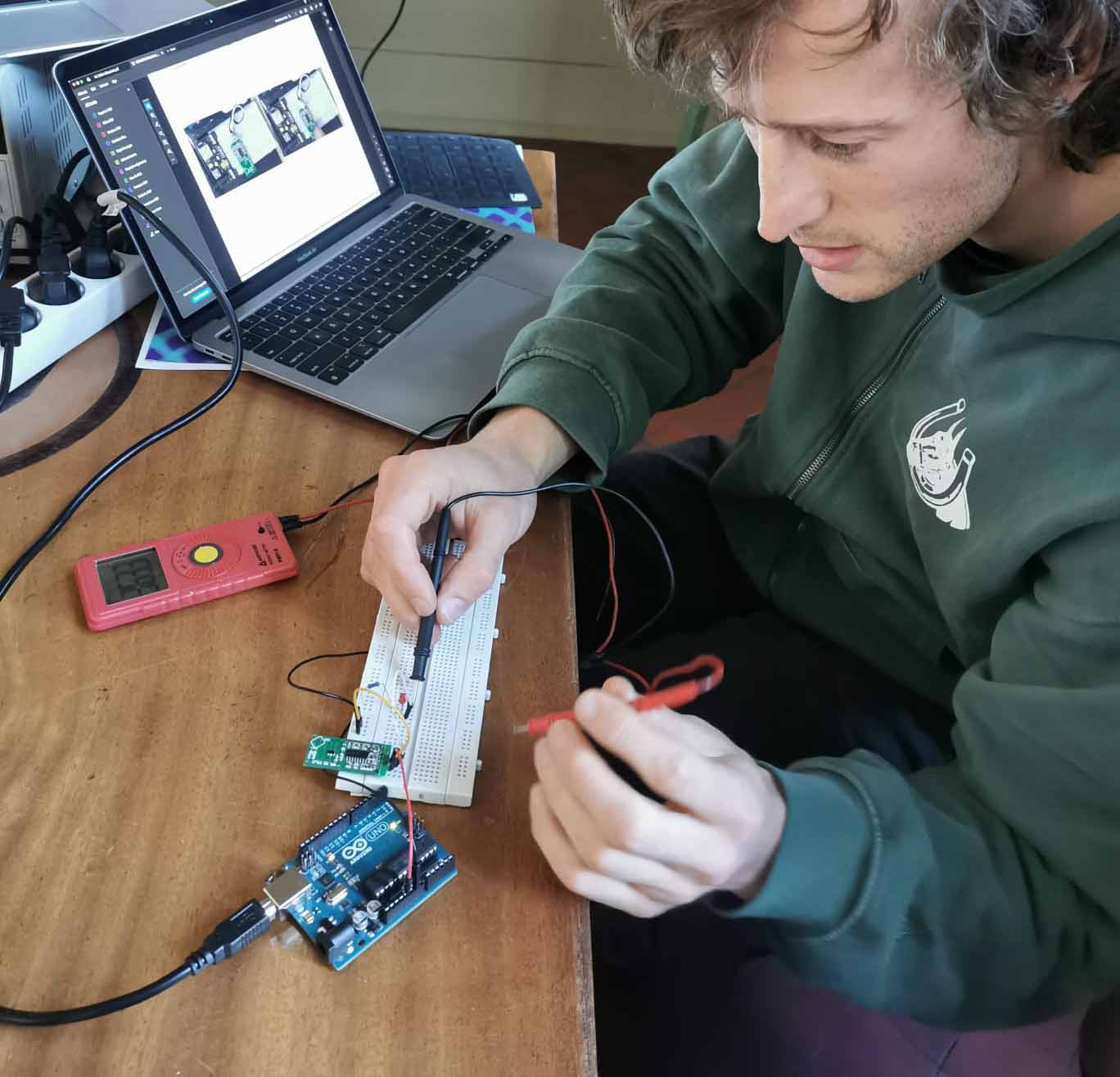
We were pretty confused about where the detection would happen. At the front, back or sides? It turned out to be on the component side of the board.
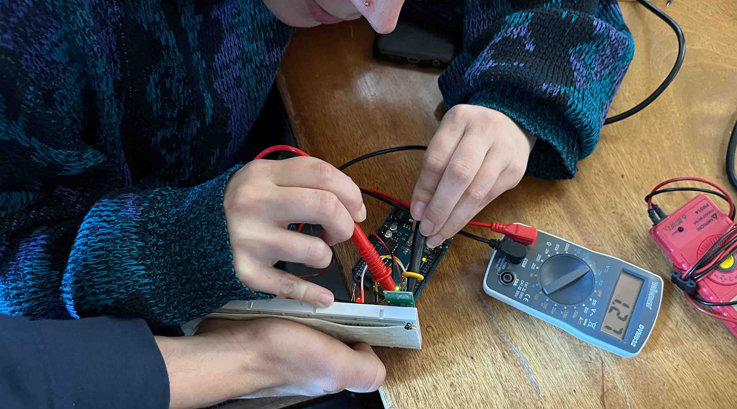
I think this board operates quite slowly. Only checking for movement every couple of seconds. We spent a lot of time thinking iot was not working. Eventually we moved on to an Ultrasonic sensor.
Ultrasonic sensor:
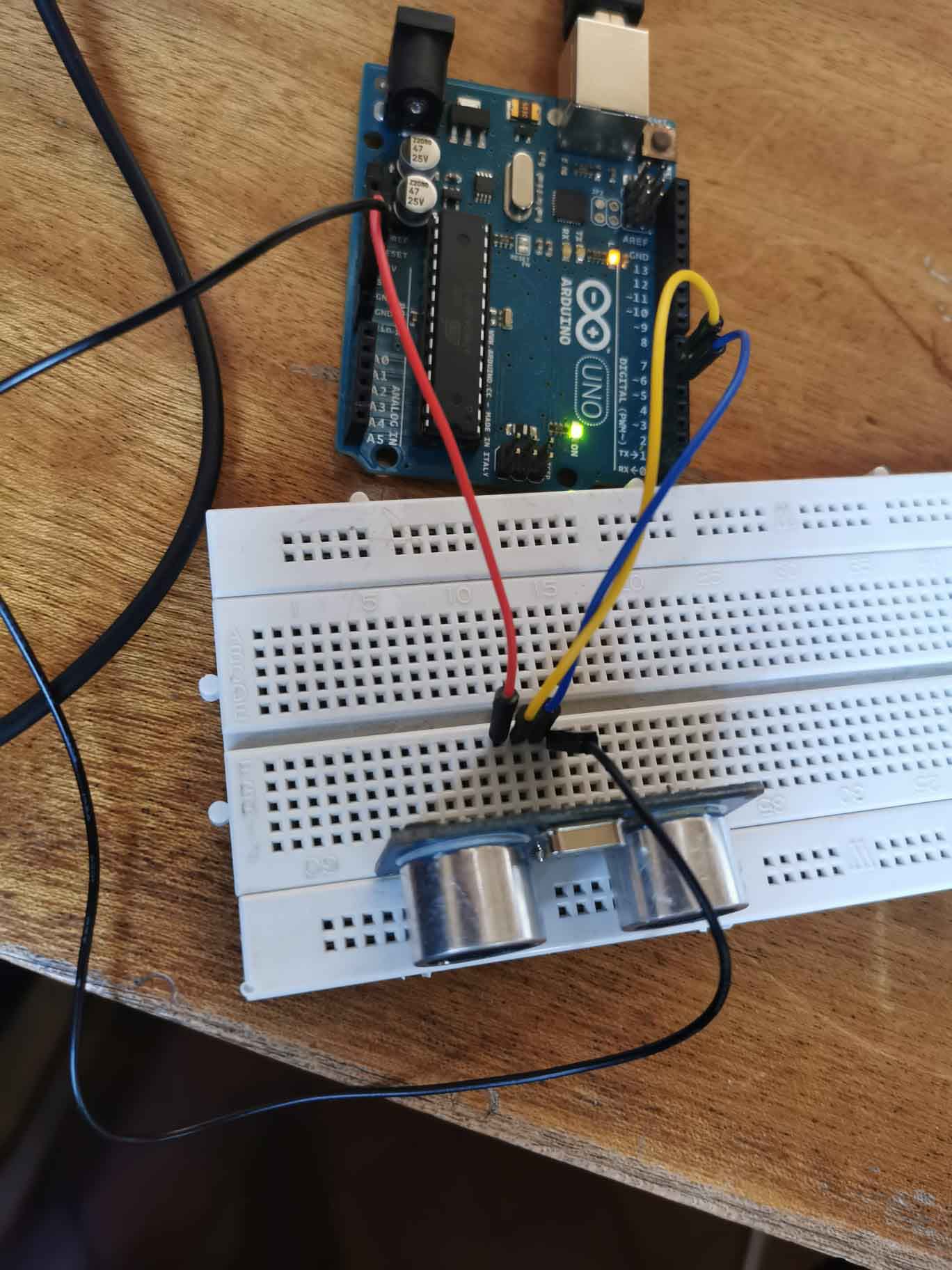
We hooked the ultrasonic sensor up to an Arduino UNO.
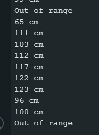
Here are the output values showing what distance the ultrasonic sensor was detecting. W ended up getting quite a lot of Out of Range values.
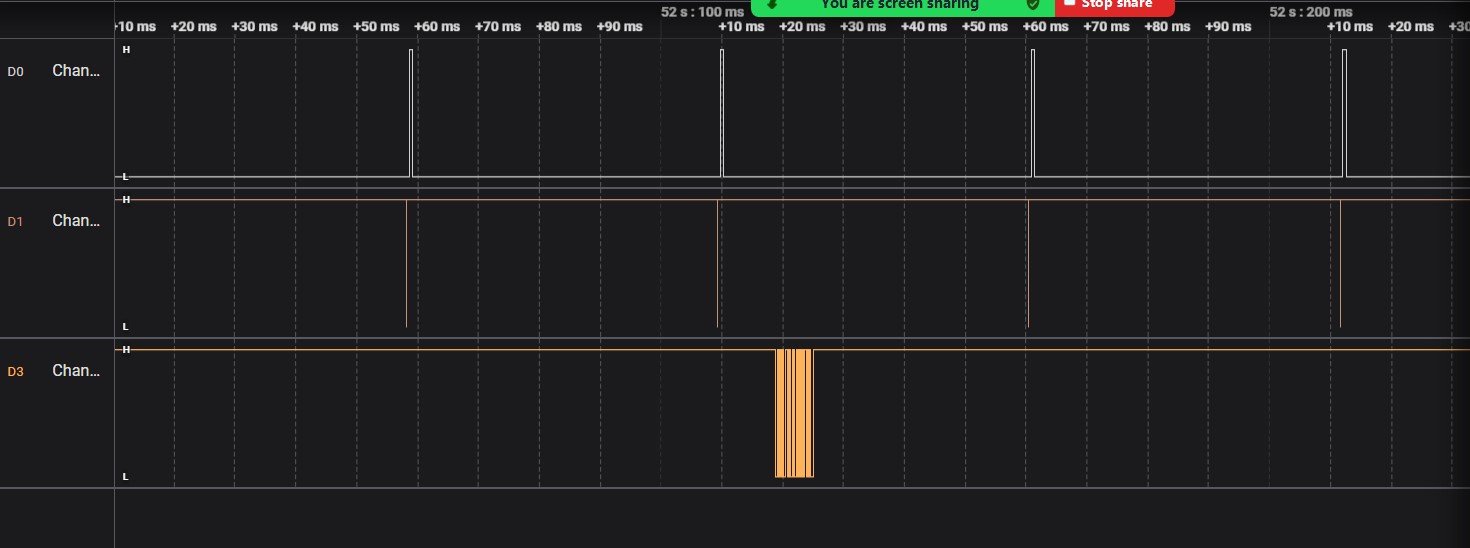
By hooking it up to a logic analyser we could see the relationship between echo and trigger signals being sent.
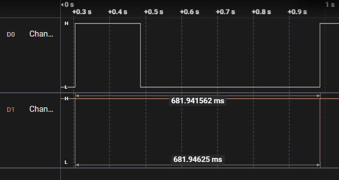
Whenever a the sensor detected an out of range value it took some time to send out the next signal again.
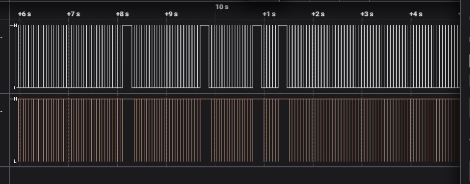
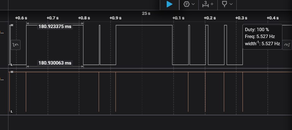
When zooming in we can see that the sensor takes 180.9 ms to process an out of range value. While it is busy witht his it does not send out another trigger, resulting in a delay.
We hooked up the logic analyser to the serial communication. The 3rd line is now showing when the values are printed in the serial monitor.
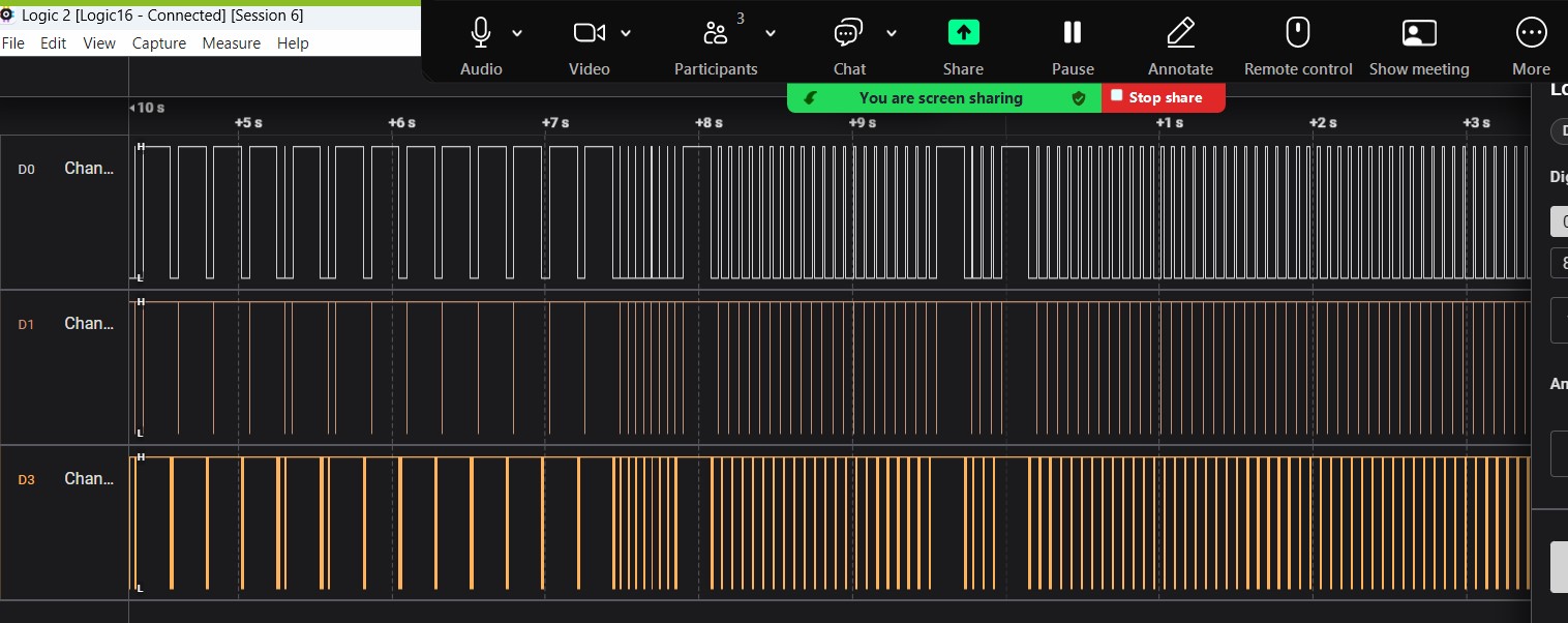
Here we moved to the other pin and Sam wrote something in the serial monitor. On the bottom line is that data displayed.
Water level control
For my final project I will need 2 inputs: a humidity sensor and something to measure if there is water in the containers or not. Since I have the humidity sensor set up from last week I focused on the water detection now.
My plan is to use the capacitive touch pins of an esp32 board to detect if there is water or not.
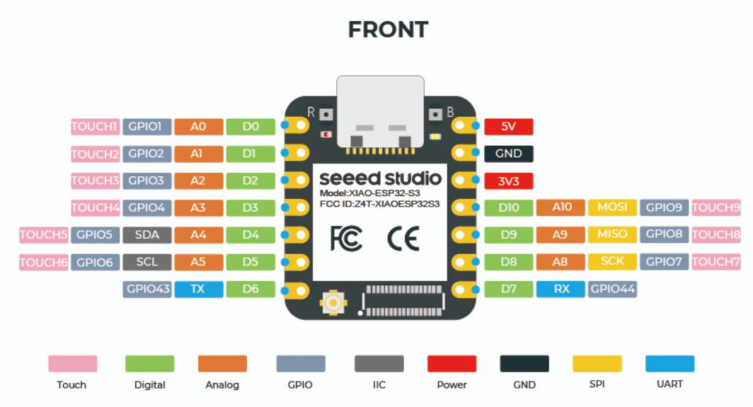
To do this I will need at least 6 touch pins. The XIAOESP32-S3 has 9 so this is the one I will be using.
Pinout xiao s3:
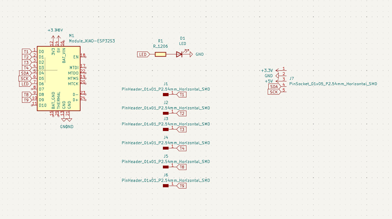
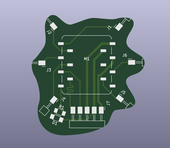
I set up a schimatic in Kikad. Added an LED to see if the board is working, 6 pinouts for the touch pins and pins for 3.3V, 5V, GND, SDA and SCK. The last 5 pins are so I can use them later on using I2C. I want tu use this as a test board.
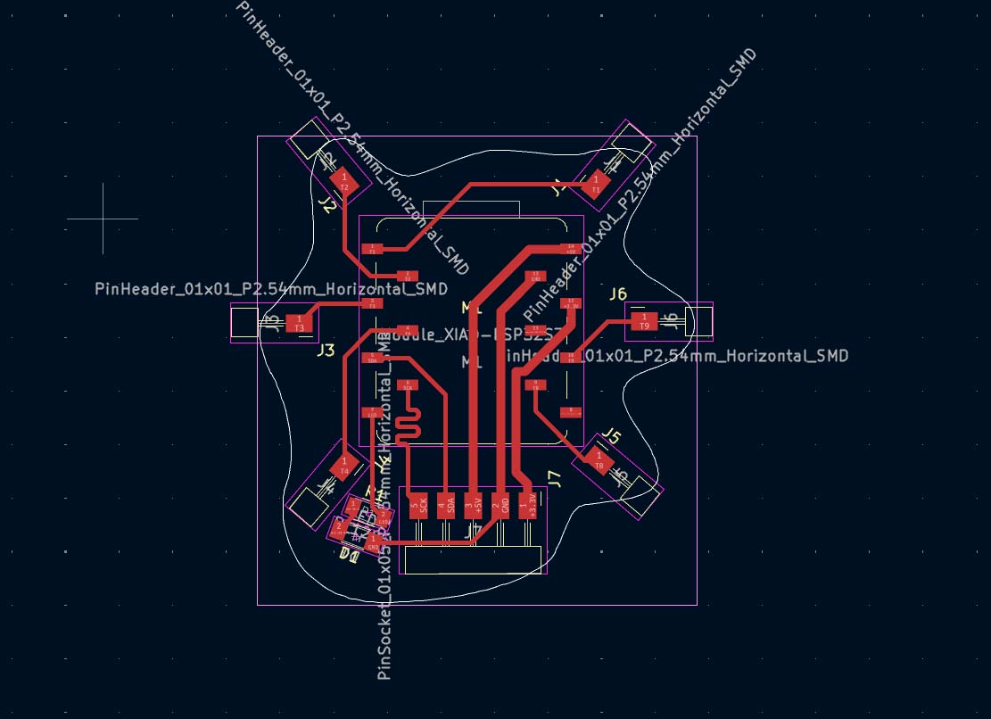
After tracing and adding edge cut the board looked like this:
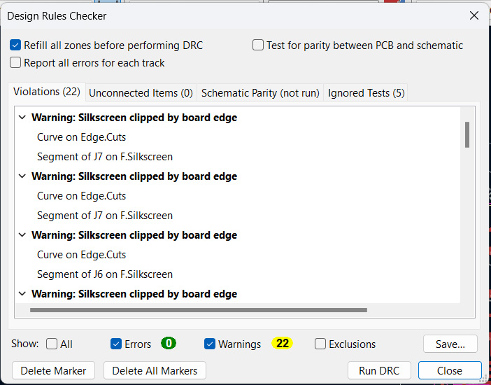
The DRC went good:
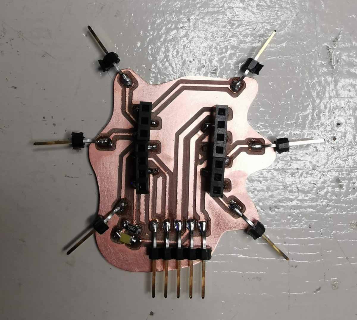
The milled board looked like this.
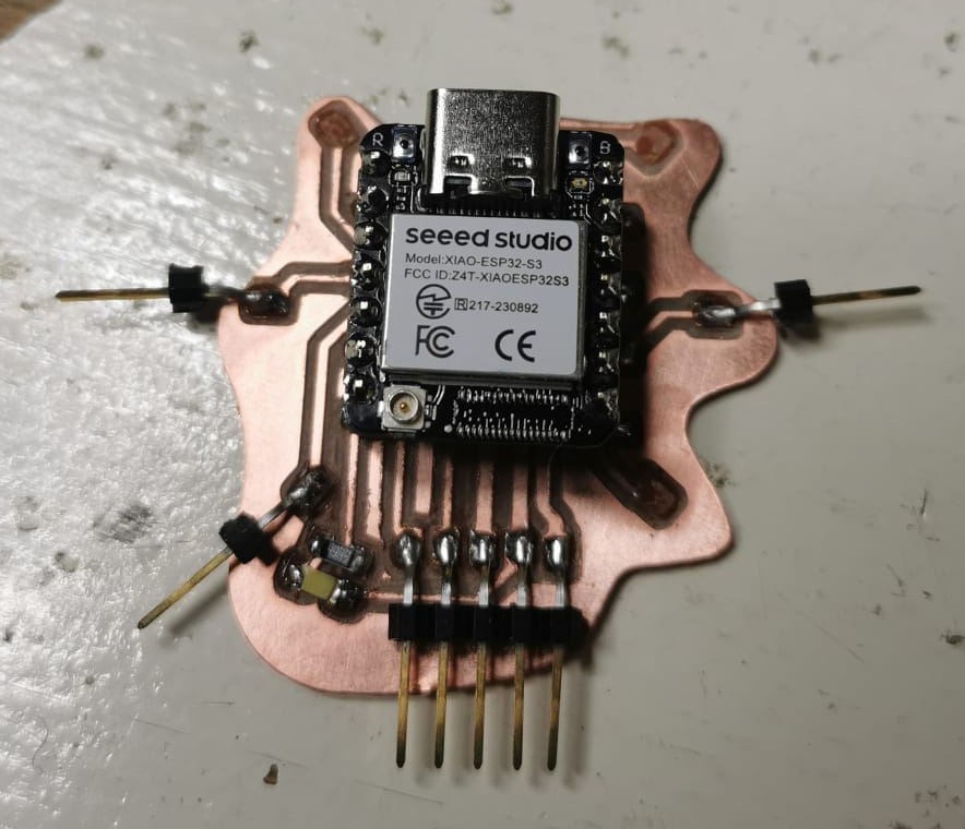
I added the XIAOESP32-S3 and modified an example code to read the pins.
void setup() {
    Serial.begin(9600);
    delay(1000); // give me time to bring up serial monitor
    Serial.println("ESP32 Touch Test");
}

void loop() {
    Serial.print("Touch 1: ");
    Serial.println(touchRead(1));  // get value of Touch 0 pin = GPIO 4
    Serial.print("Touch 2: ");
    Serial.println(touchRead(2));  // get value of Touch 0 pin = GPIO 4
    Serial.print("Touch 3: ");
    Serial.println(touchRead(3));  // get value of Touch 0 pin = GPIO 4
    Serial.print("Touch 4: ");
    Serial.println(touchRead(4));  // get value of Touch 0 pin = GPIO 4
    Serial.print("Touch 7: ");
    Serial.println(touchRead(7));  // get value of Touch 0 pin = GPIO 4
    Serial.print("Touch 8: ");
    Serial.println(touchRead(8));  // get value of Touch 0 pin = GPIO 4
delay(1000);
}
From this i could see that when the pins are dry and not in contact with anything they carry a value of a bit over 2000. When held by a human the value goes way up: into teh the 18000s and higher. When I added them to water the value went to a bit over 4000. I can therefore put a threshold in my code at 4000. If the value drops below this then the humidifiers should not turn on.
Mistakes
I brought the board home yesterday because I thought I would test something out in the evening. I didn't end up doing anything with it so the only thing I achieved was to brake off 3 pins i transportation.
The copper pads had also fallen off, but i attempted to solder the pins back on aling the lines. And it worked
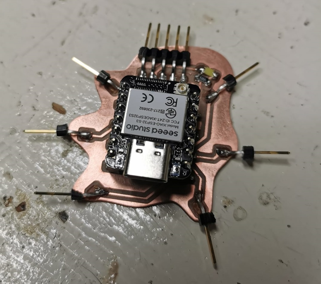
for about 30 seconds. When I went to attch wires 2 of them fell off. I am down to 4 touch pins, but for testing purposes this in enough.
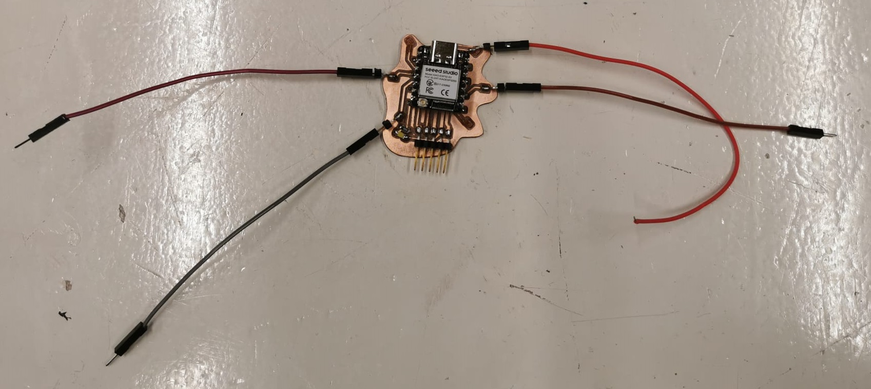
Adjustments
I went to do a final test of the board. I now saw that the threshold between in water and out of water is around 30000, not 3000. And they the values are going lower this time. I will need to test and adjust this in my final set up.

This is the test code for now:
void setup() {
    Serial.begin(9600);
    delay(1000); // give me time to bring up serial monitor
    Serial.println("ESP32 Touch Test");
}

void loop() {

if (touchRead(3) < 30000){
    Serial.print("Touch 3: ");
    Serial.print(touchRead(3));
    Serial.println("    OUT OF WATER");
} else {
    Serial.print("Touch 3: ");
    erial.print(touchRead(3));
    Serial.println("    ACTIVE");
}
delay(50);

if (touchRead(4) < 30000){
    Serial.print("Touch 4: ");
    Serial.print(touchRead(4));
    Serial.println("    OUT OF WATER");
} else {
    Serial.print("Touch 4: ");
    Serial.print(touchRead(4));
    Serial.println("    ACTIVE");
}
delay(50);

if (touchRead(8) < 30000){
    Serial.print("Touch 8: ");
    Serial.print(touchRead(8));
    Serial.println("    OUT OF WATER");
} else {
    Serial.print("Touch 8: ");
    Serial.print(touchRead(8));
    Serial.println("    ACTIVE");
}
delay(1000);
}
With this I can see clearer if the pins are active or not.


I'm glad to be able to use the touch pins of the ESP as a safety mechanism in my humidifier. Since the humidity sensor from last week is working I now have my 2 input devices working. I need to be more careful with transportation of boards in the future and to design them more robustly.
Since there are more touch pins available from teh S3 I'm concidering if the humidifier could be turned on bu touch? Or can it also function as a lamp? There are still some spirals to complete before I can concider that. Will keep it in mind for later.
Next up for me (electronics wise) now is to develop the ultrasonic mist maker module and connect the parts together using ESP NOW.