Computer Controlled machining (CNC)
This week we are going BIG!
But before we cold go big we needed to get introduced to the most dangerous machine in the Fablab: the ShopBot CNC milling machine.
SAFETY
First things first: SAFETY!
We have been fed with stories of accidents the last few days. Ranging from missing fingers to fires, explosions and hair stuck to spindles resulting in death.
I will kick this documentation page off with some safety rules:
- NEVER leave the machine while it's running
- Long hair? - tie it up! (people have died from getting their hair caught in the machine)
- No loose clothing
- If you are not feeling good (stressed and tired) then you may not use the machine.
- Wear safety glasses when operating the ShopBot.
- Make sure nothing is on the table or leaning against it.
- Always keep a hand on the space bar - this is the pause button
- Make sure to not run into the metal screws. This can cause sparks and fire or even an explotion
- If a spark is created immediately stop the machine using the emergency button and shut of the ventilation. Go to the dust collection bag. If it is on fire close the bag to limit oxygen, yell a warning out of the window and throw the bag outside. Even if there is no fire keep the bag closed and walk outside keeping and eye on it.
Safety principles:
1: Investigate risks - what are they? 2: Remove risk cause - remove if possible 3: Reduce risk effect - if removing is not possible the reduce the risk 4: Use protection - if risk cannot get further reduced: wear protection
Checklist when using machine
I will explain further down everything we went though this week, but I know I will use this page to make sure I am doing all the steps when CNC milling in the future. So here is a checklist:
Step 1 Self check
Make sure you are not wearing any loose clothing that can get caught, is your hair tied up? Clothes for working in? Safety glasses close by? ANd most importantly: are you feeling zen? You should not be milling if you are tired, stressed or in general not feeling good. It demands a lot of attention and a calm mind.
Step 2 Clean the surroundings
Make sure there is no wood leaning against the machine, nothing on the rails, nothing on the machine.
Step 3 Prepare the sacrificial layer
Sand down any bumps (carefully) around holes without creating a dent and vacuum the plate.
Step 4 Prepare your plate
Vacuum the bottom of the plate you will be milling
Step 5 Milling bit
Attach the milling bit you will be using, make sure to place the collet in the nut and click it in before adding the millling bit. Make sure its all fastened and that the dust skirt is up.
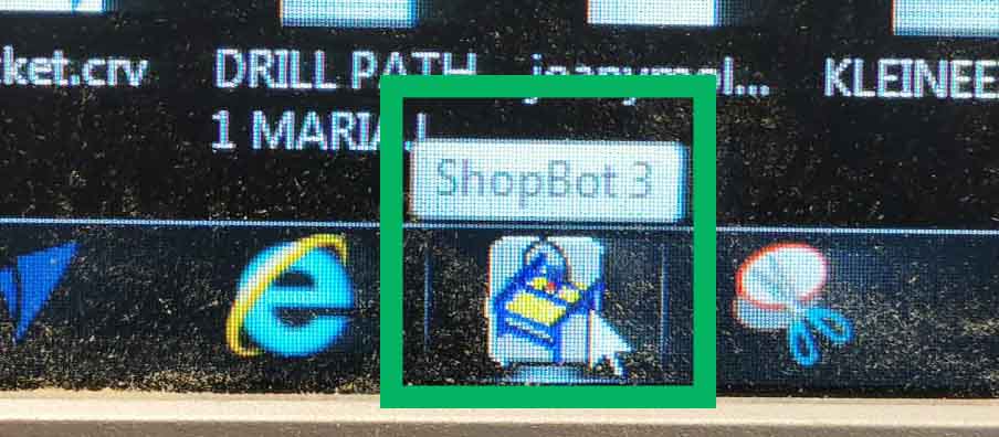
Step 6 Turn on ShopBot and open ShopBot 3
Flick the switch on the right hand side and open ShopBot 3
Step 7 Set Z axis to Zero
Using the metal piece next to the spindle. Test that the machine is registering the metal and place it under the bit on the sacrificial layer and click the Z zero Icon.
Step 8 Move milling head out of the way
Using the arrows on the keyboard navigate the milling head out of the way. To open menu click: K.
Step 9 Place material on the sacrificial layer
Make sure there is no dust and small pieces making it uneven.
Step 10 Choose your starting position
Using the arrows move the milling head to where you want to start.
Step 11 Open your holes file
Open the .spb file containing the marking of holes in Shopbot 3
Step 12 2nd check
Double check the surroundings and yourself. No loose hair, clothing ect and nothing leaning on the machine. Grab your safety goggles.
Step 13 Turn on vacuum
Using the button on the front of the ShopBot
Step 14 Turn on spindle
Insert key on right hand side of ShopBot and turn it.
Step 15 Mill the holes
Press start. The milling will start. Be sure you have set the x and y direction and starting point in your document correctly.
Step 16 Turn off the spindle
Turn off the spindle and move the milling head out of the way.
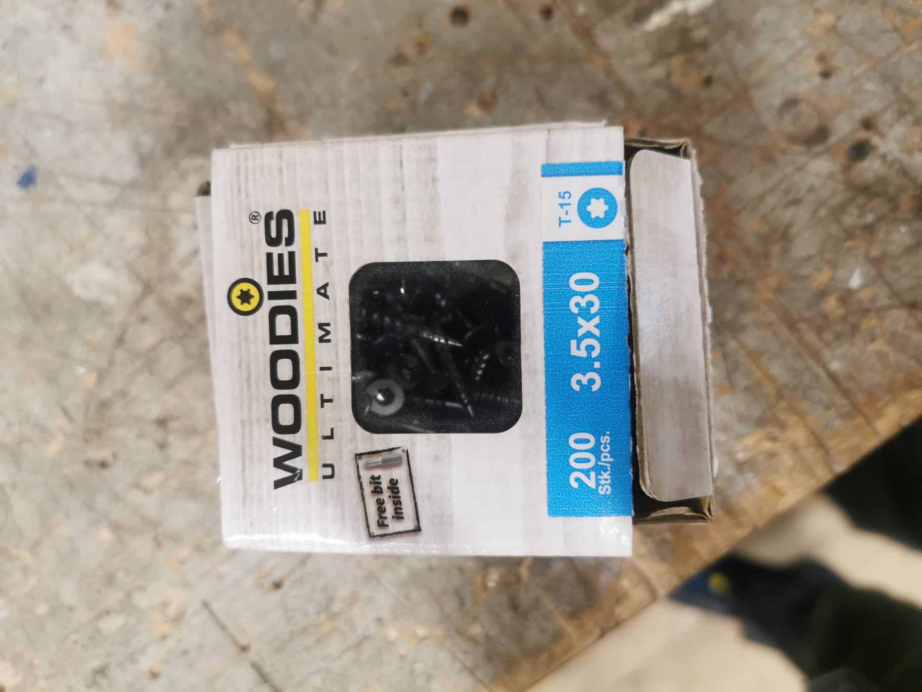
Step 17 Screw in woodies
Attach the plate to the sacrificial layer using woodies and a drill.
Step 18 Home last job
Click the home last job icon to bring the milling head to the starting position for your milling.
Step 19 Open next file
Open the .spb file containing your main milling job.
Step 20 Check surroundings
Chack teh surroundings. Nothing neaning and nothing left on the table or the rails.
Step 20 Turn on spindle
Using key on right hand side of ShopBot.
Step 21 Start milling
remember to keep a hand on space bar to pause if the milling head is in th air and be ready to press teh emergency stop button on the front of the machine.
Step 22 Turn off the spindle
Step 23 Turn off the vacuum
Step 24 Unscrew woodies
Unscrew the screws and remove the wood. Check that no screws are left in the sacrificial layer and return the woodies to their box.
Step 25 Vacuum the bed
Step 26 Remove parts from tabs
Step 27 Post processing
Sand and stain(if needed) the wood.
Preparation
First we were showed the different parts on and around the ShopBot. Starting with the dustbag at the back. It is connected to a vacuum that sucks away all the woodchips whan milling. It can ba found in the back of the room behind the white door.
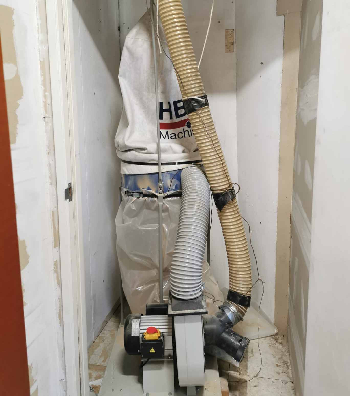
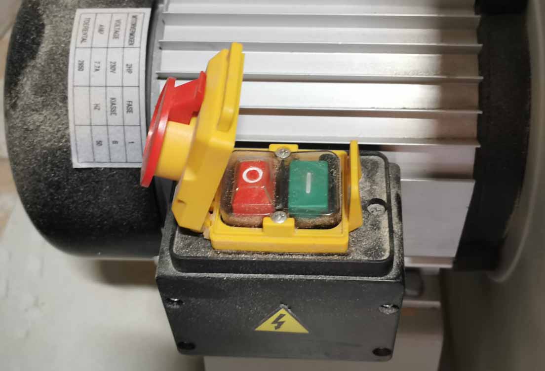
In order to turn it on open the box with the red lid and press the green button. Then leave the lid leaning in the top. If the lid is pushed down the red button will be pressed stopping the vaccuum:
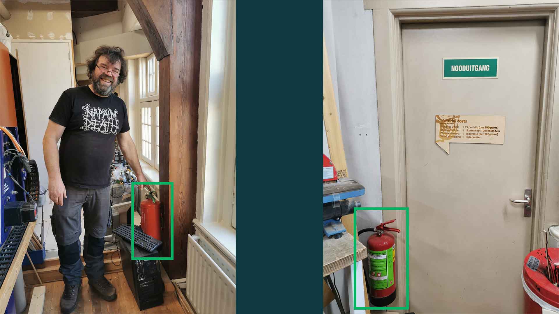
This big bad of dust also creates a big fire hazard. If the milling bit hist a screw sparks will get sucked into the dust bag and it might explode or ignite. It is therefore important to know where the fire extinguishers are. We have 2, one next to the ShopBot and another next to the emergency exit on the other side of the room.
If a screw is hit or you see sparks quickly turn of the vacuum, remove the bag of dust and inspect it. If it is burning close it to limit oxygen flow. Shout a warning out the window and throw it out. If it is not on fire: close the bag to limit oxygen flow and keep it under observation. I could start melting.
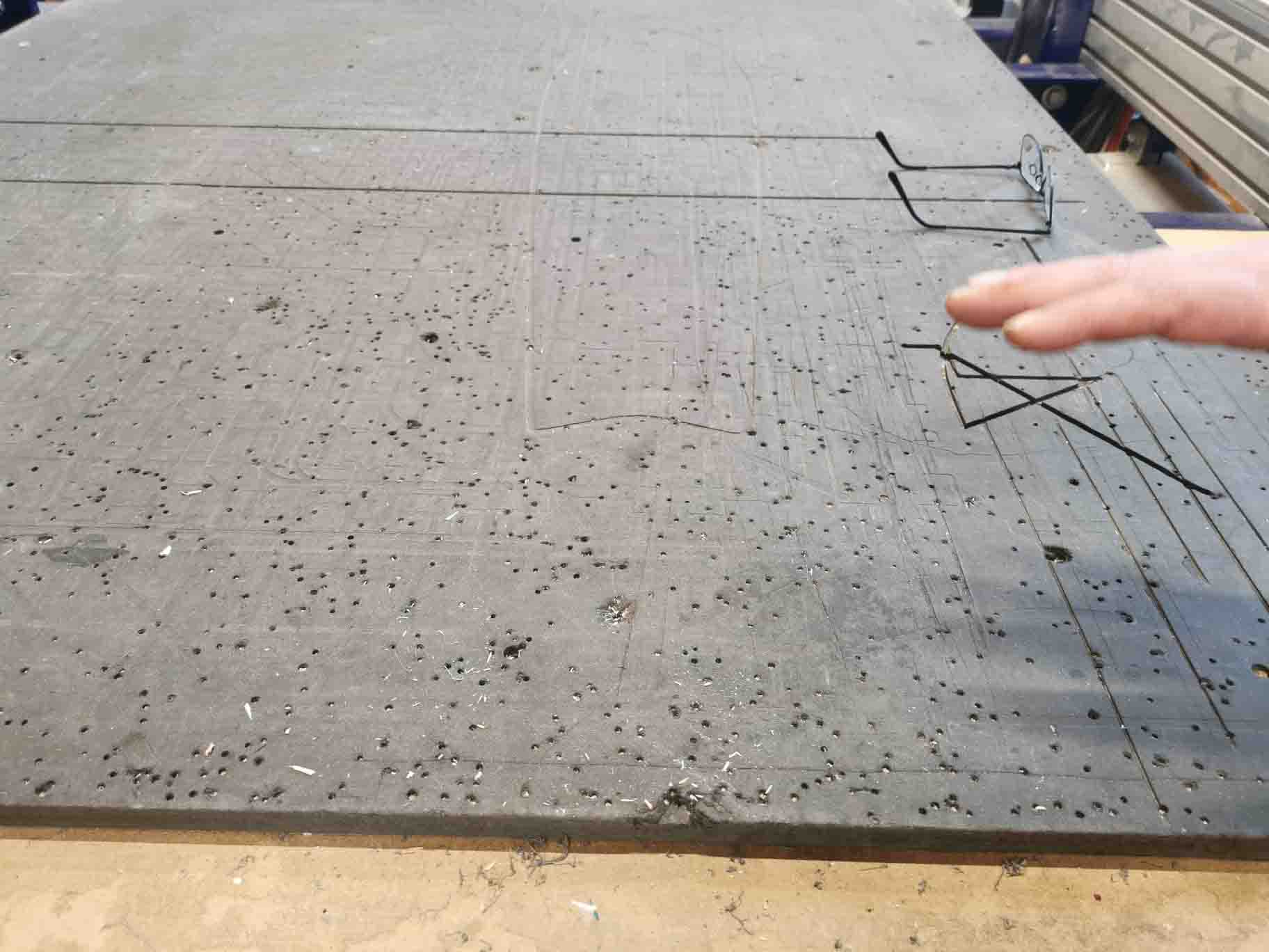
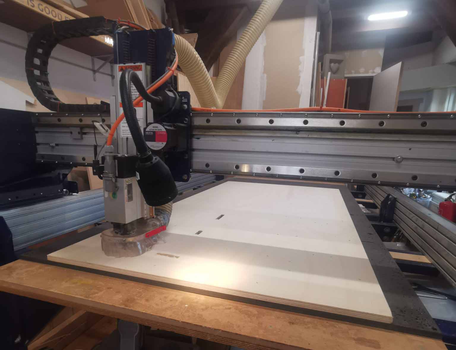
On top of the ShopBot there is a larfe MDF plate called the sacrificial layer. We use this to protect the bed of the milling amchine and to attach the material when milling. Before placing the material you need to sand down any bumps left by screws in previous milling and vacuum the plate.
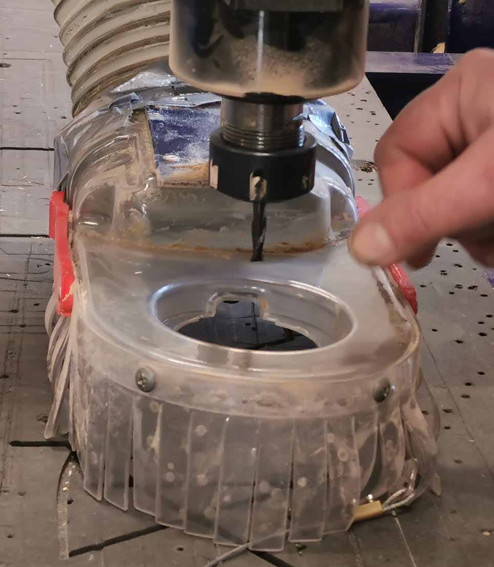
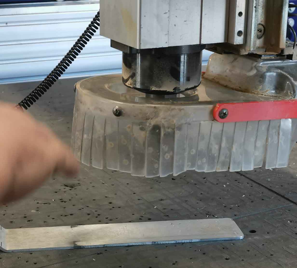
In order to get to the spindle, where the milling bit is located, undo the butterfly-screw at the back of the milling head.
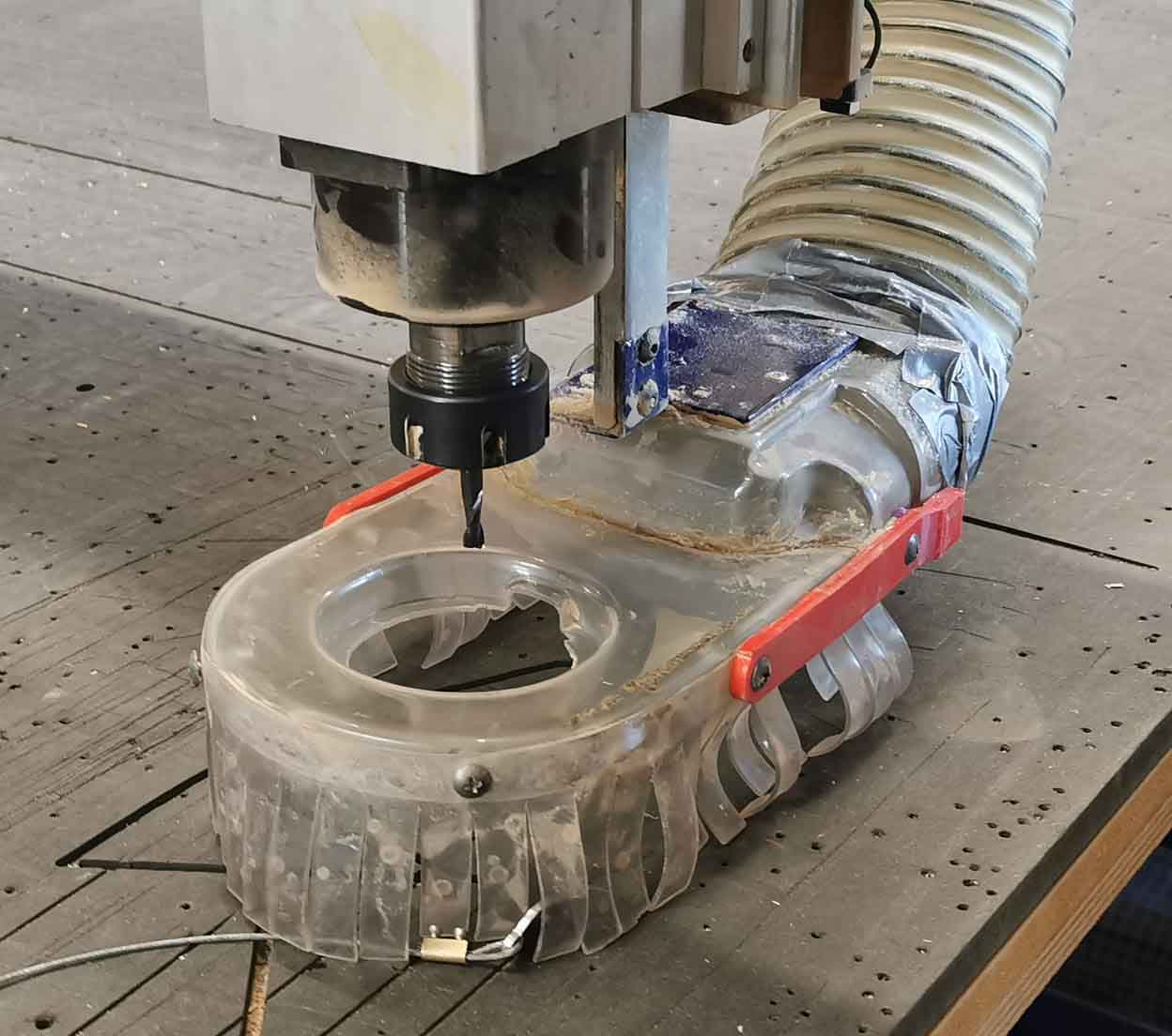
Move the dust skirt down:
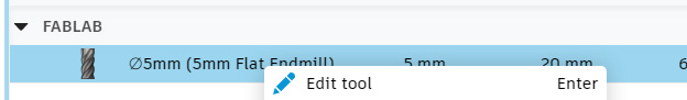
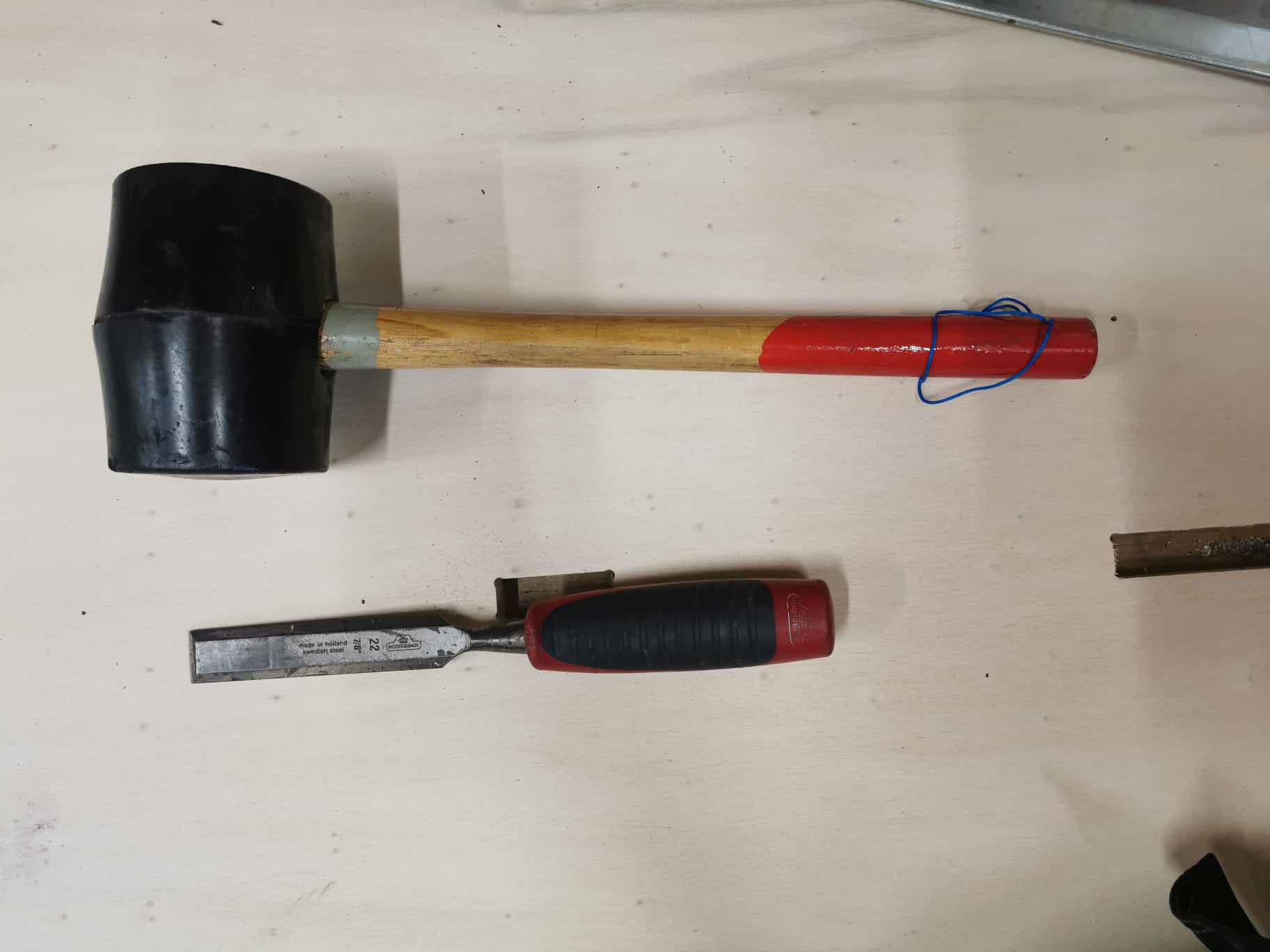
To loosen the nut use this tool with is connected to a key. The key is needed to start the spindle. They are connected to avoid anyone getting hurt.
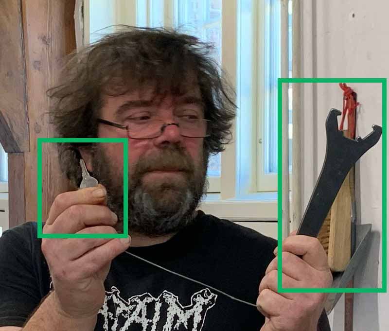
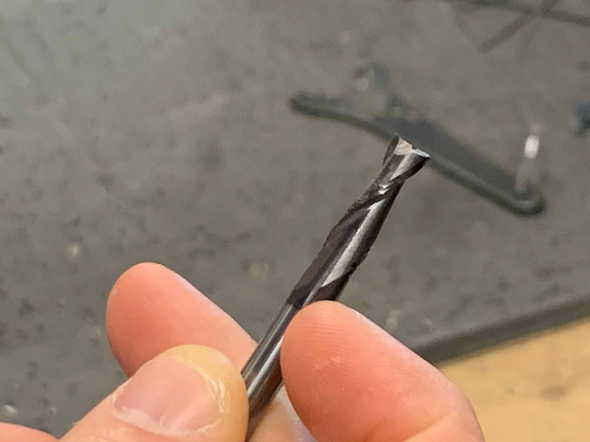
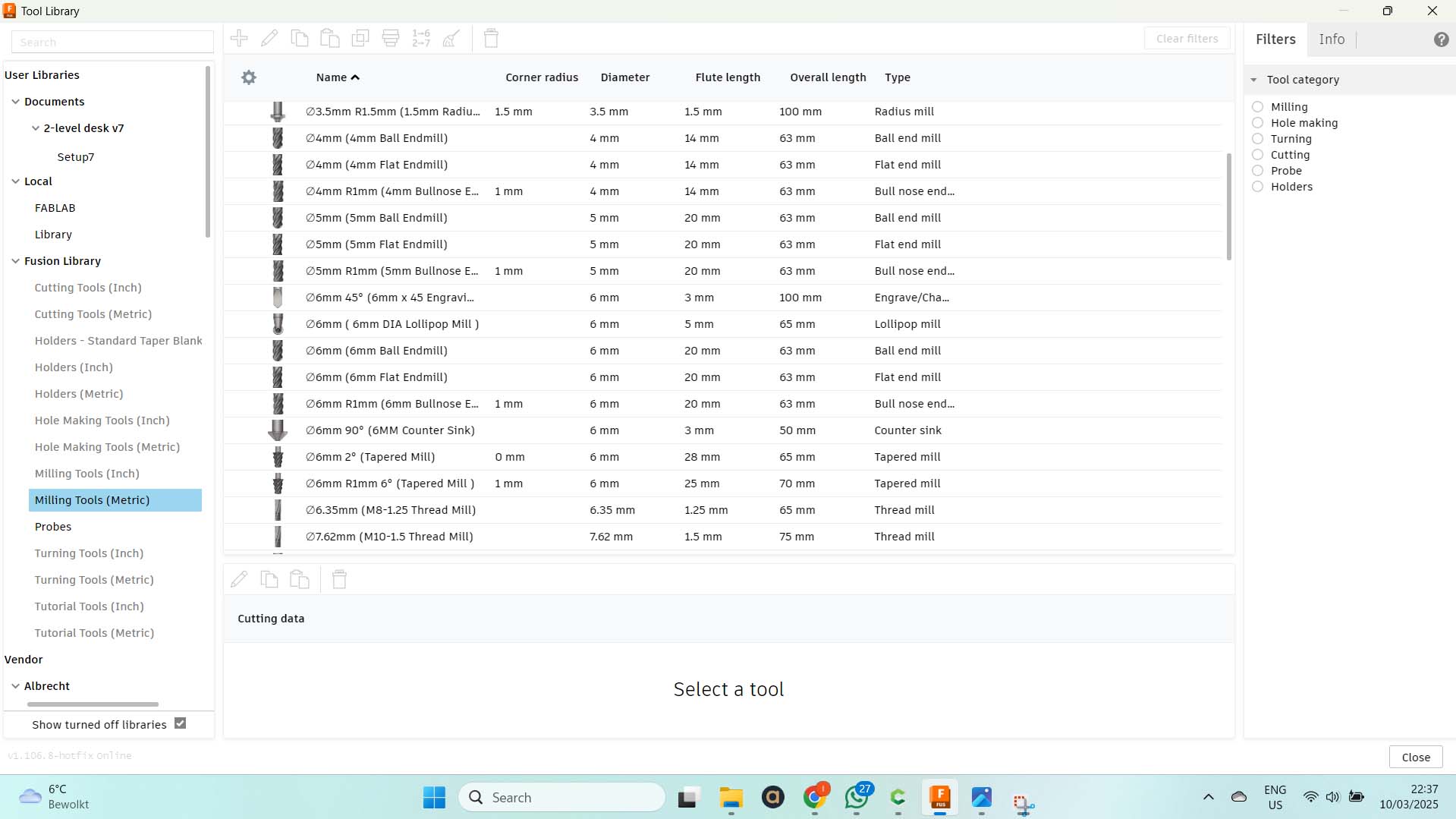
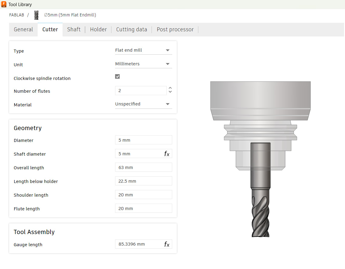
We are using a 5mm 2 flute flat end milling bit.
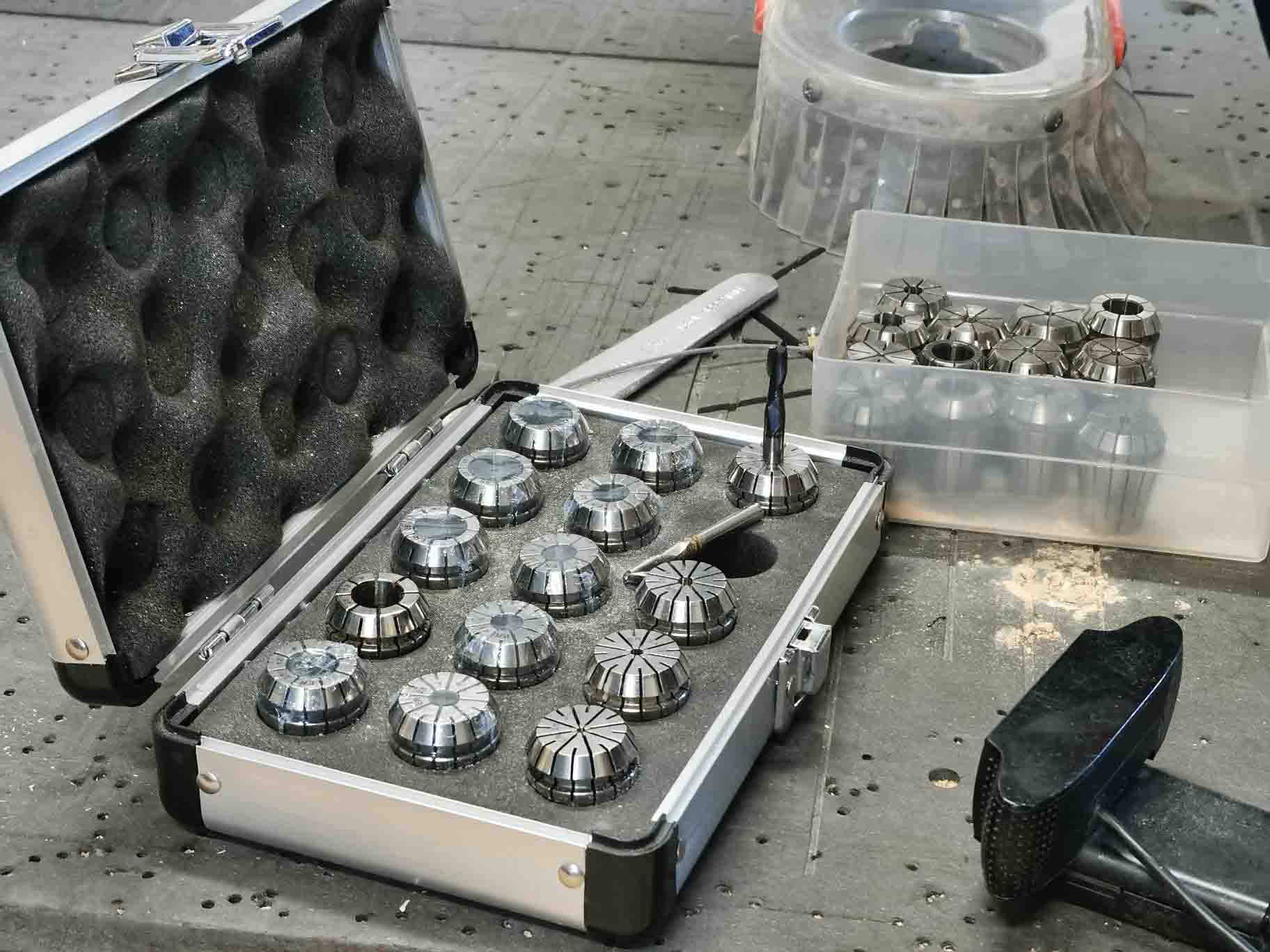
Choose the right collet for the bit. We have 2 sets. Use the ont in the silver box. These are in metric measurements. The set in the drawer is in US measurements.
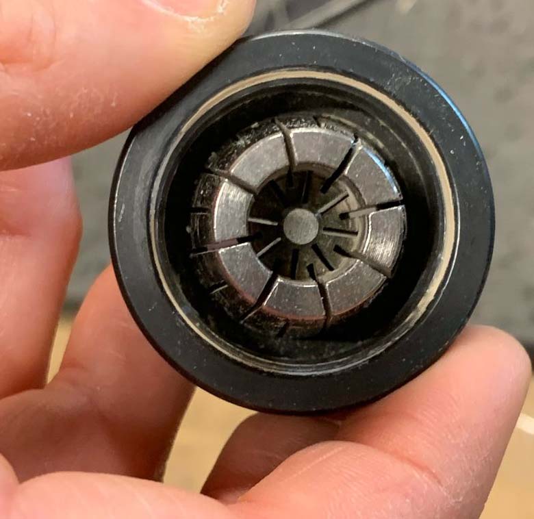
Chack thaty the clamping nut is dust free, place the collet in it and press until you hear a click. Then add the milling bit from the front. It is important to use this order if not they will not be properly attached.
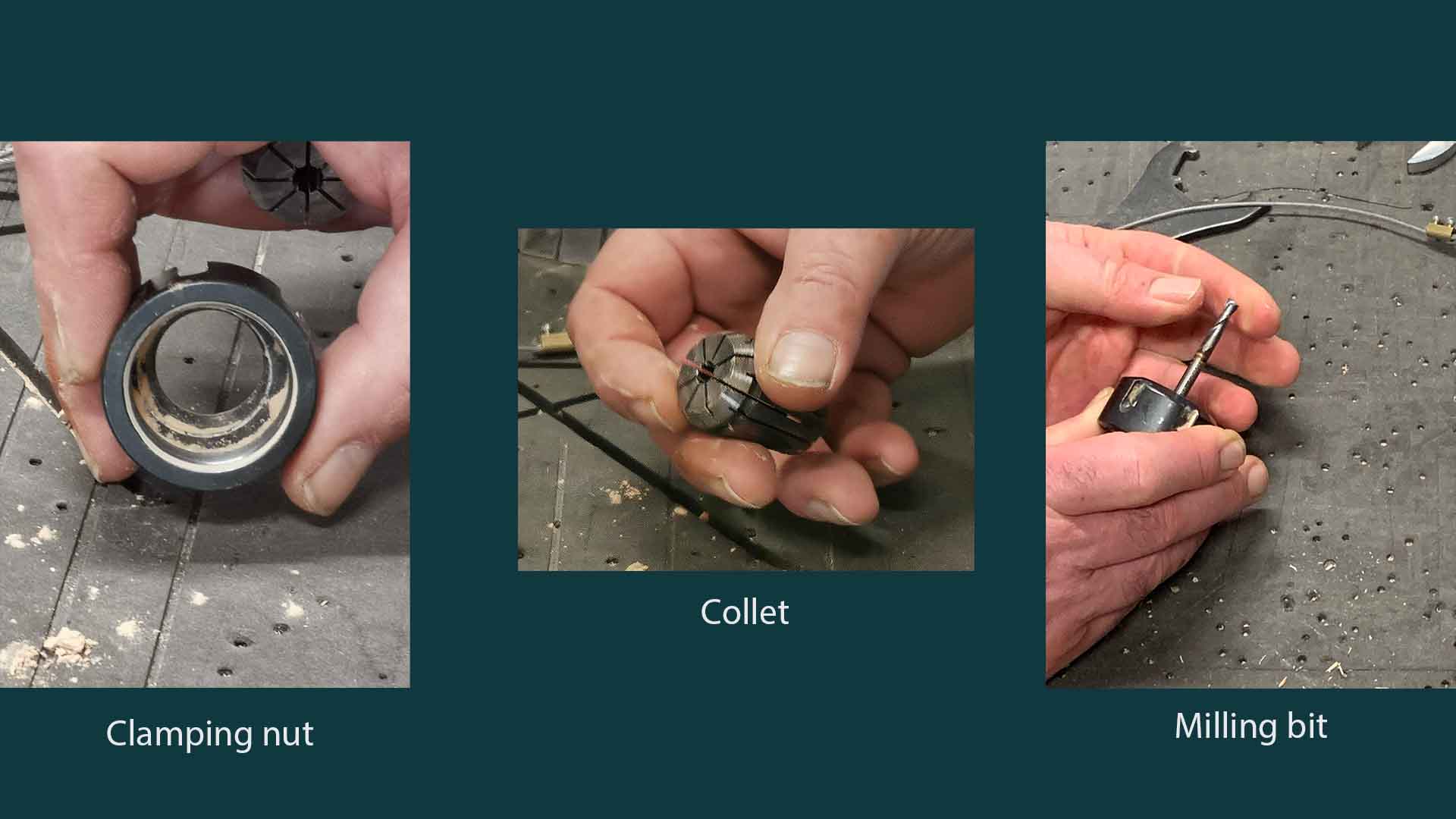
Make sure the bit is at least as far in as the narrow part of the collet. It can also be furter in. You shpuld always allow for a bit of extra length to be sure it goes all the way through the material.
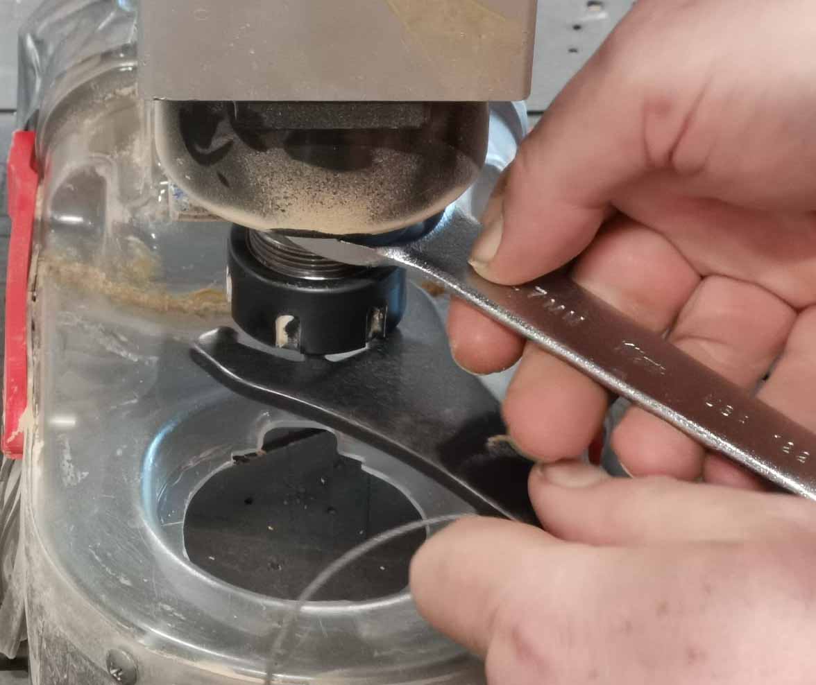
Screw the nut with the other pieces attached into the milling head.
Fasten with the tools attached tot he key. Make sure to get ti tight enough, but not so tight that we cannot loosen it again. and place the tools on the box on the right hand side of teh ShopBot.
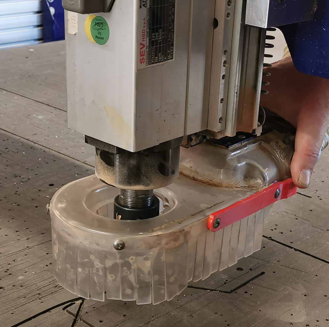
Pull up and fasten the dustskirt.
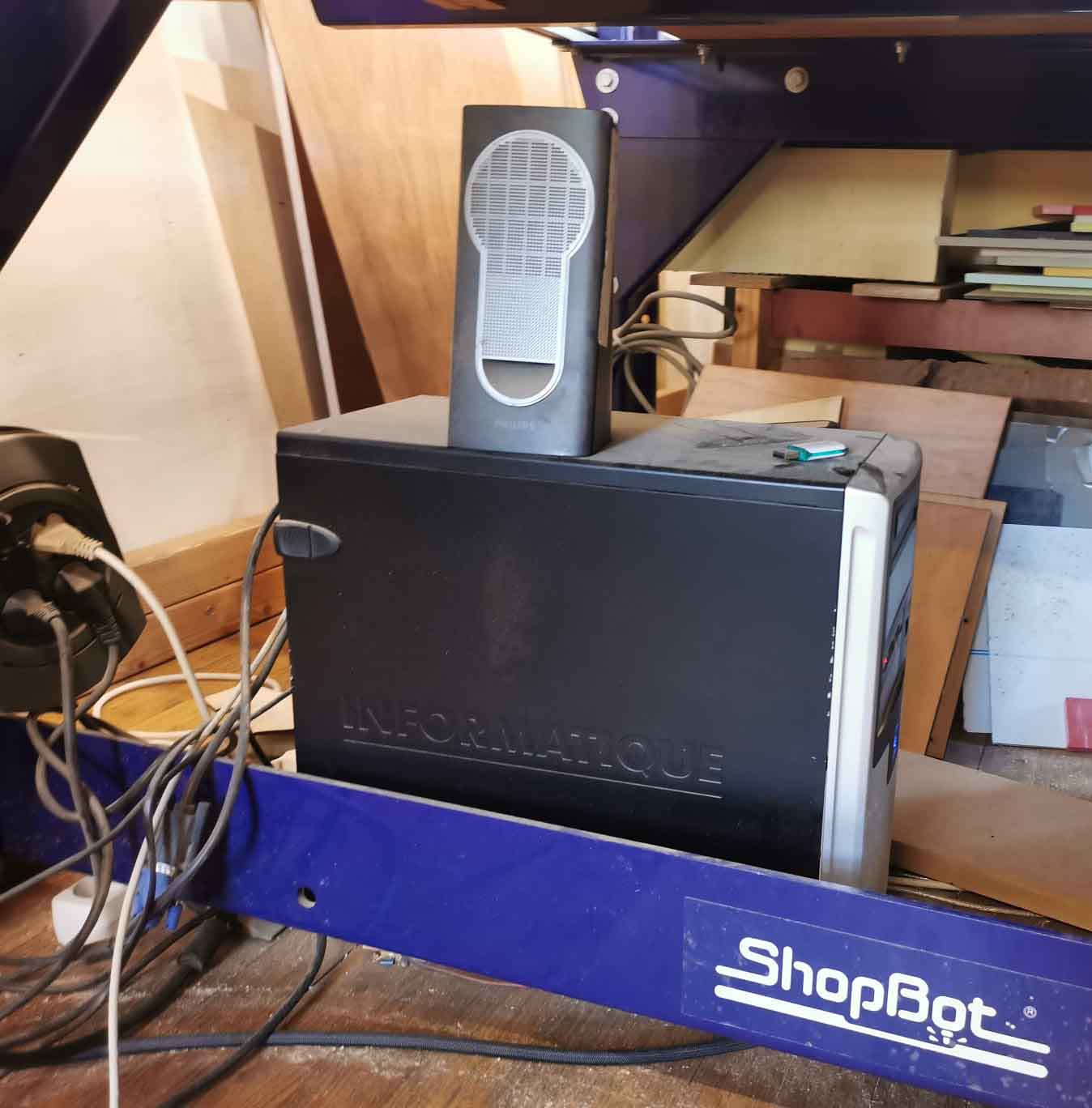
Shopbot setup
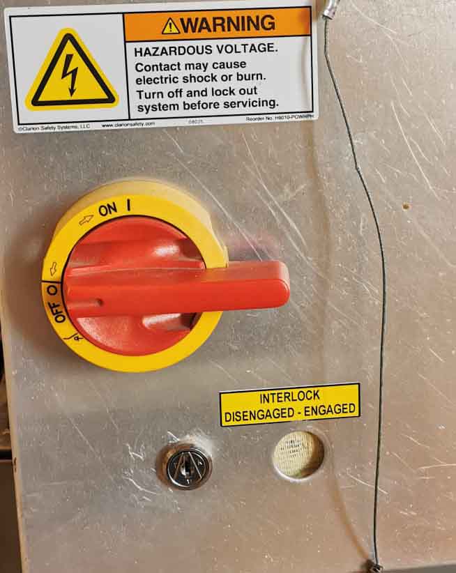
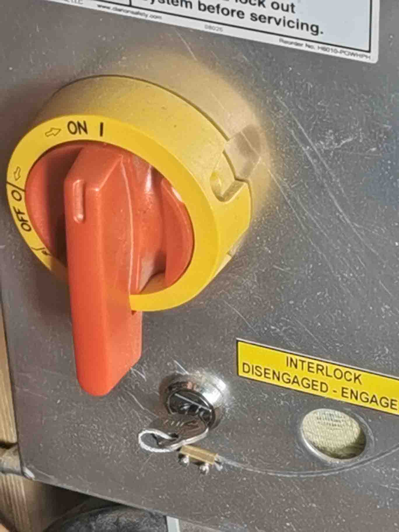
Next up is the computer. To use the ShopBot 3 program the CNC mill needs to be on. Switch the large red switch on the right hand side to ON, on the box where you put the tools for the milling head.
Turn on the computer under the machine.
Open the ShopBot 3 software.
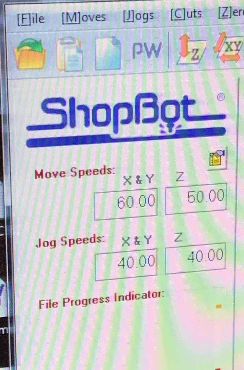
Chack that the move and jog speeds are alright before moving the milling head anywhere.
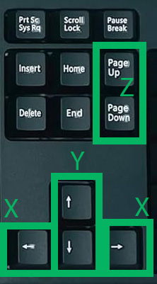
In the yellow square press K. This opens a yellow panel allowing you to move the milling head around.
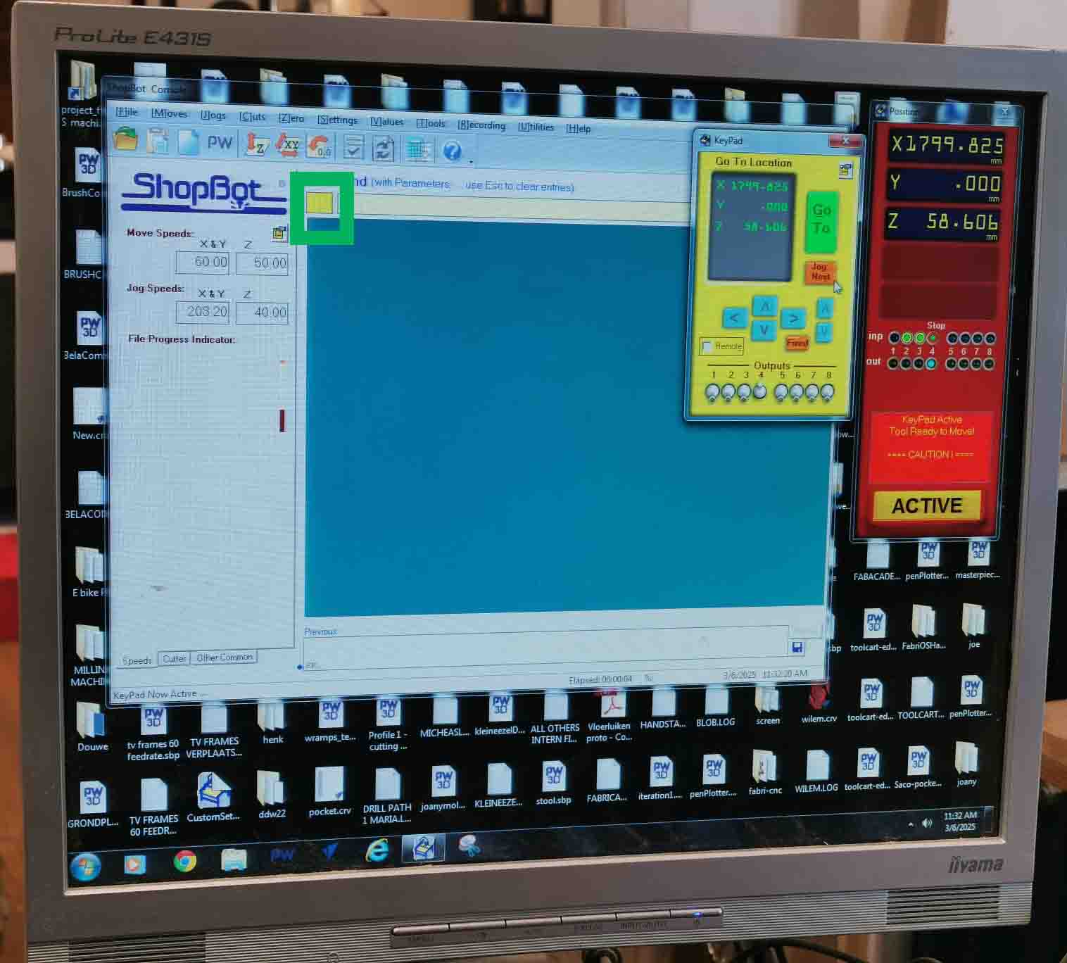
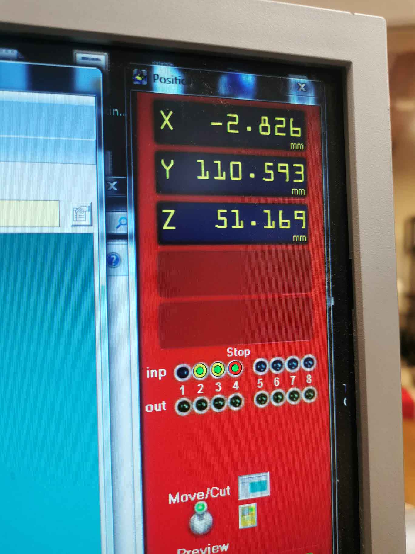
Move the X and Y axis by using the arrows on the keyboard and the Y axis with the Page Up and Page Down buttons. The computer is ar an angle to the shopbot to make the arrows correspond to the right directions to avoid confusion and mistakes.
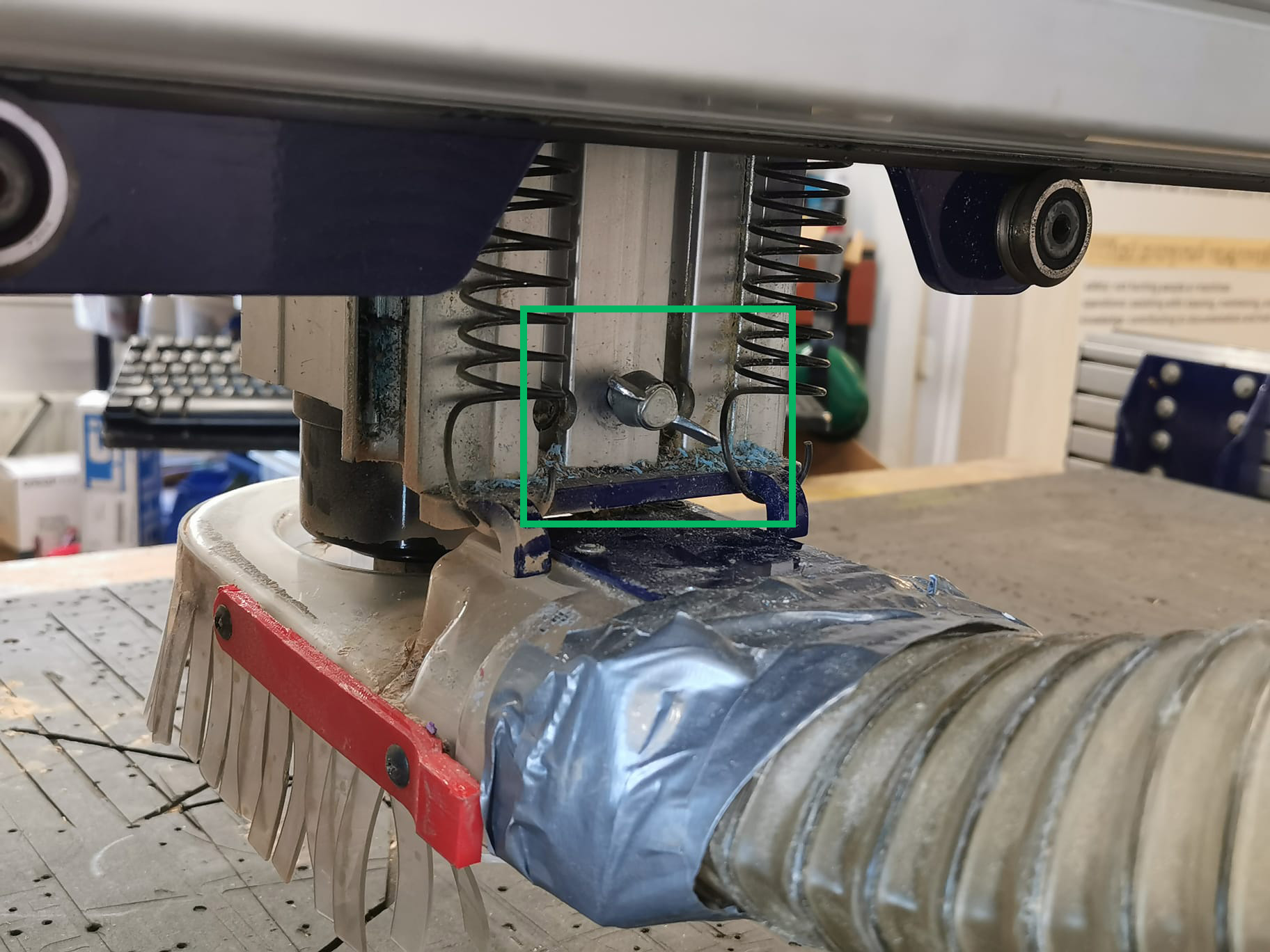
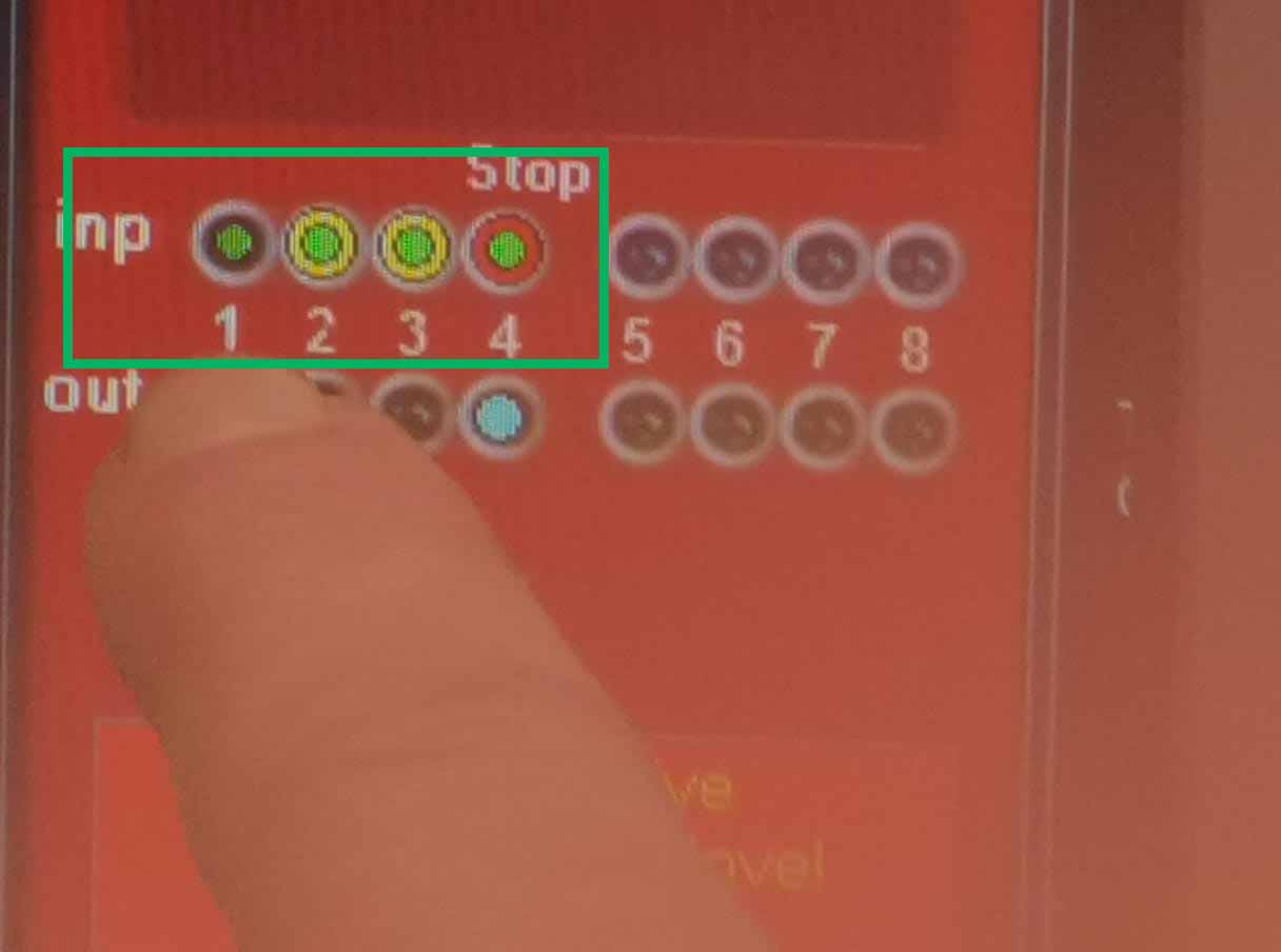
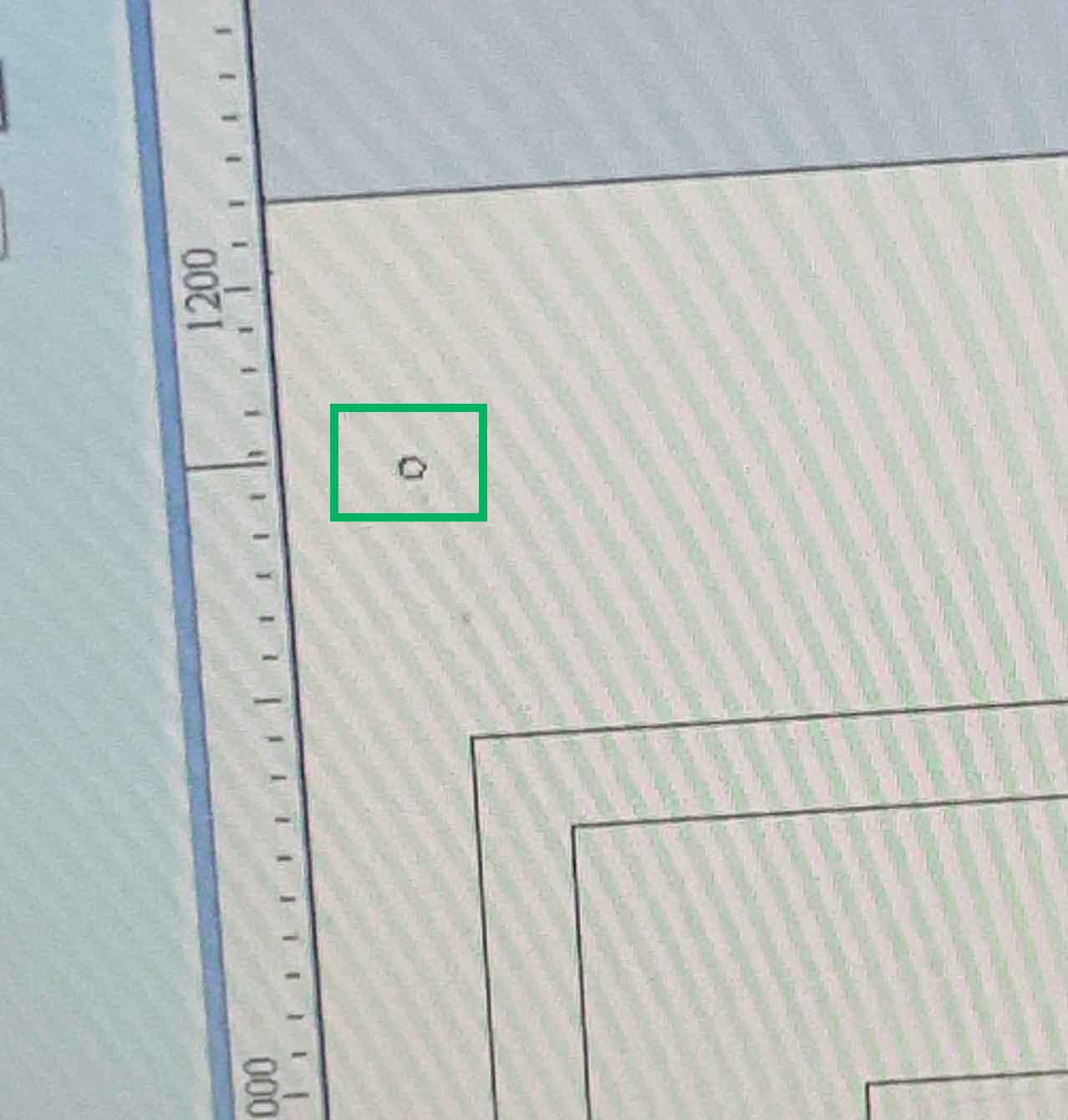
Now its time to Zero the Z axis. First thake the piece of metal on the left side of the milling head and touch it to the drill bit.
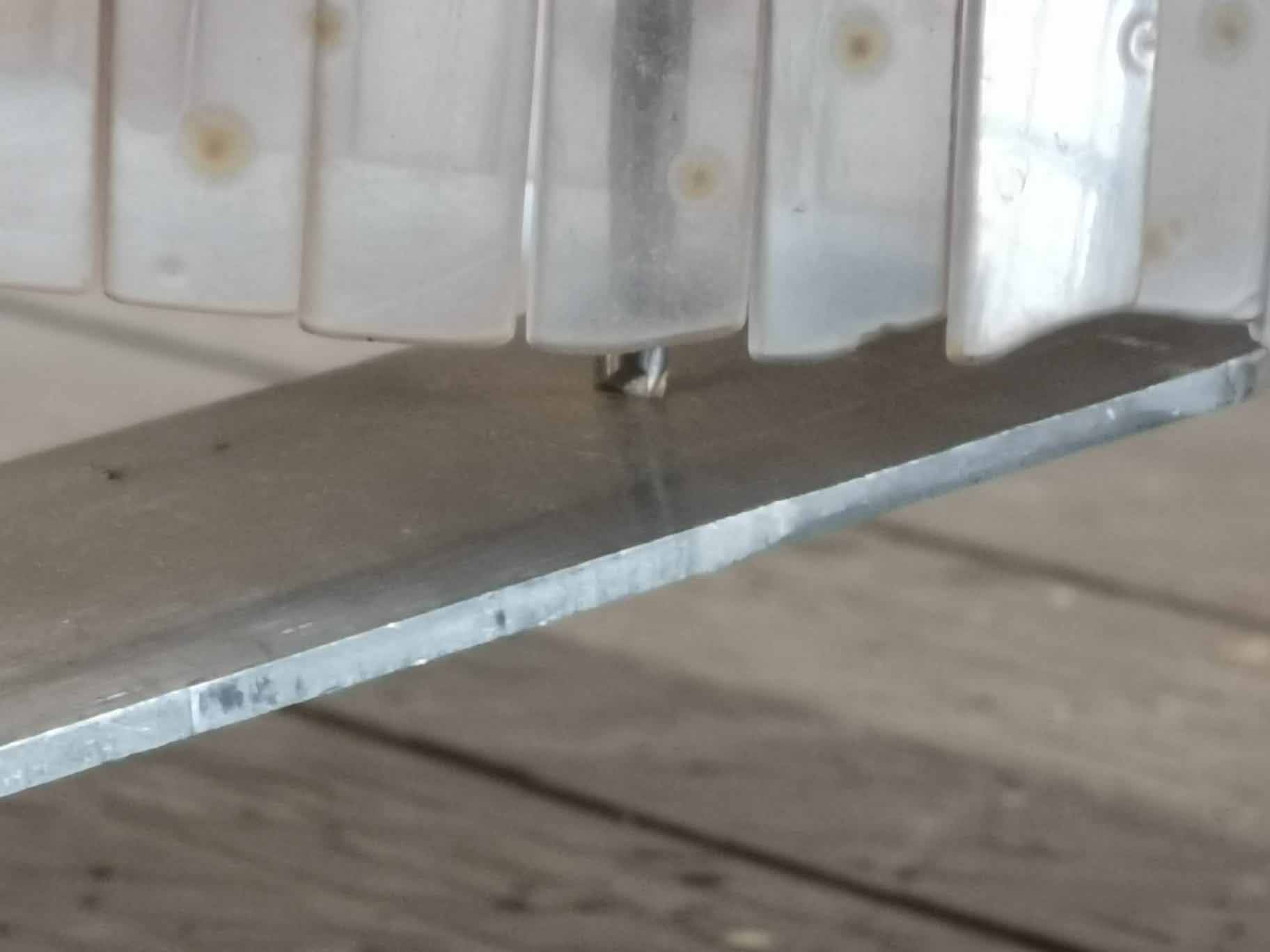
When it touches these green dots should appear. It means that the machin knows it's touching the metal plate.
Now place the plate under the milling bit. Make sure it really is directly under. Sometimes it can help to move the z axis a bit down to be sure.
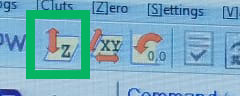
Click the Zero z-axis Icon in ShopBot 3. Once you start it, it will keep going until it meets the metal. It's therefore very important to make sure they are properly alighed.
After Zeroing the Z axis place your material on the bed.
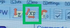
Bring the X and Y axis to their zero position using the button below, and move them wotht he arrows to you ideal starting position.
VCarve
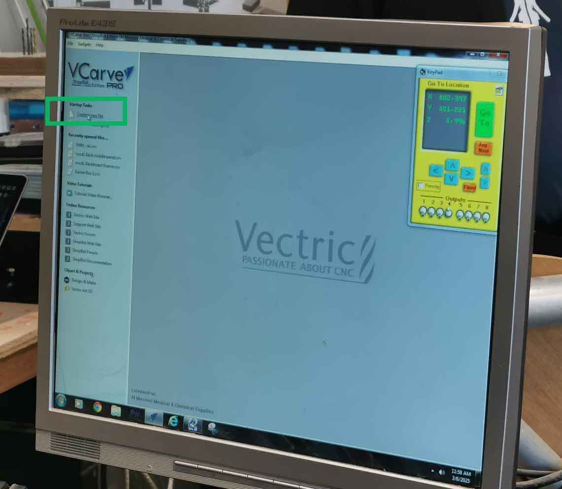
To determine how the machine will mill we need to set the paths it will take in the program Vcarve. It is pinned to the taskbar. Open the program and open a new file.
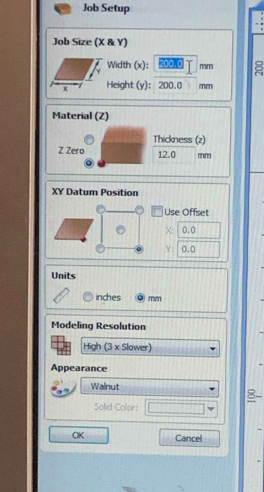
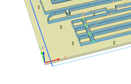
First detirmine how big you work area will be. That is the size of your material and the thickness of it. In this menu you also decide on the XY starting position. Keep in mind that you are sitting witht the ShopBot to your right at a 90 degree angle so you starting position should be as showed under. Something to not is that the maximum plate size we can use is 2240mm by 1220 mm. The last panel is for 3D rendering and wont affect the actual milling.
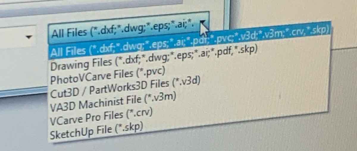
Here are all the accetped file formats.
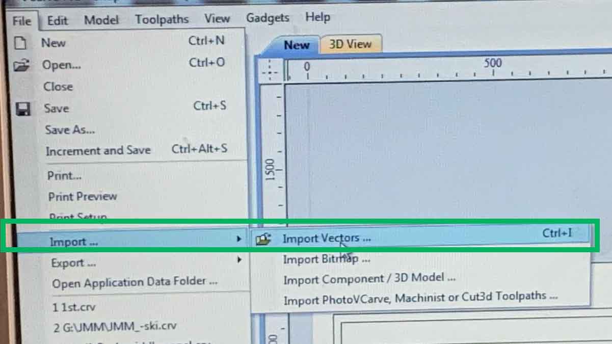
You can choose to assmeble you file in Vcarve or it is possible to import it as a vector by clicking: file, Import and import vector:
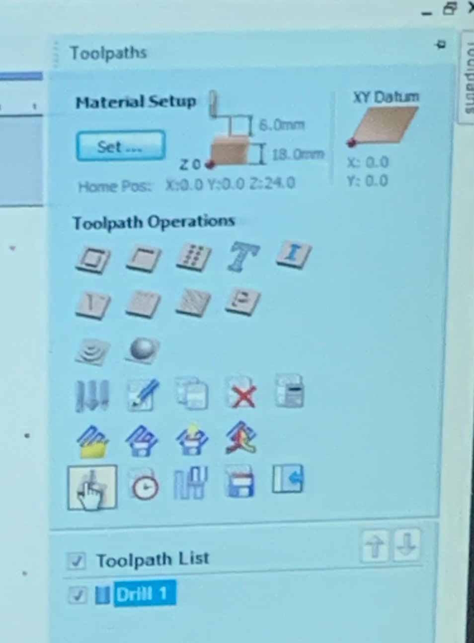
In the material setup you can see the options for creating toolpaths.
Once your file is imported add the places you want to mark for adding screws. Make sure these are not interfering with the design and won't cause any collisions. The wholes should be 5 mm, or the same as your bit.
FOr the marks you want to choose the Drilling Toolpath setting. Cut at 2 mm depth, just for marking. Select the Fab Academy End Mill 5 mm. and click calculate.
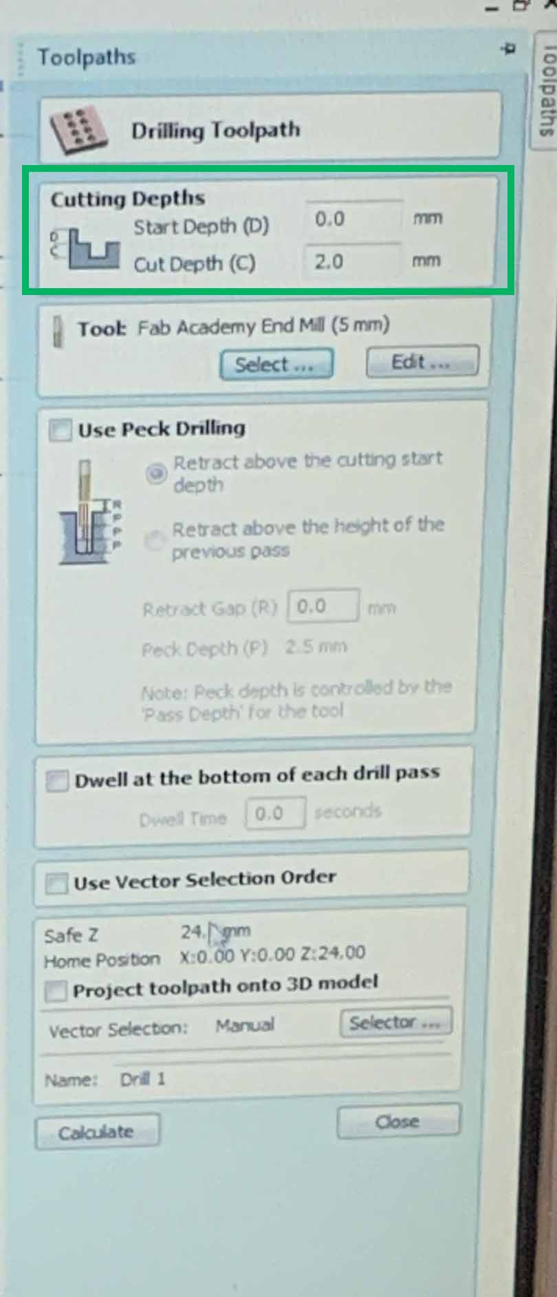
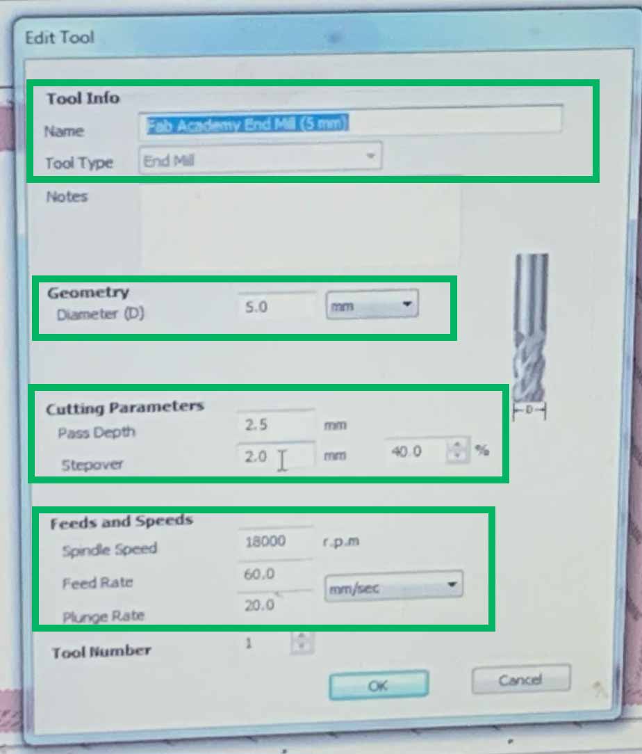
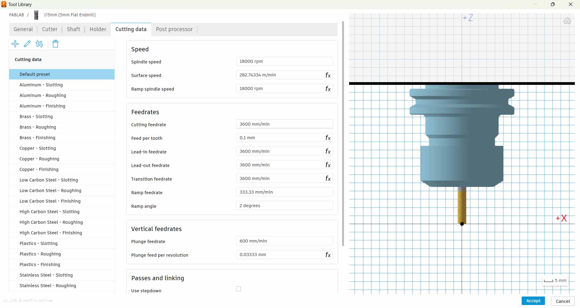
When choosing the right millign bit you also get to the menu where it is possible to adjust settings for the size of the bit you are using, how deep each cut is (pass depth), stepover (how each line overlaps), plunge rate, feed rate and spindle speed.
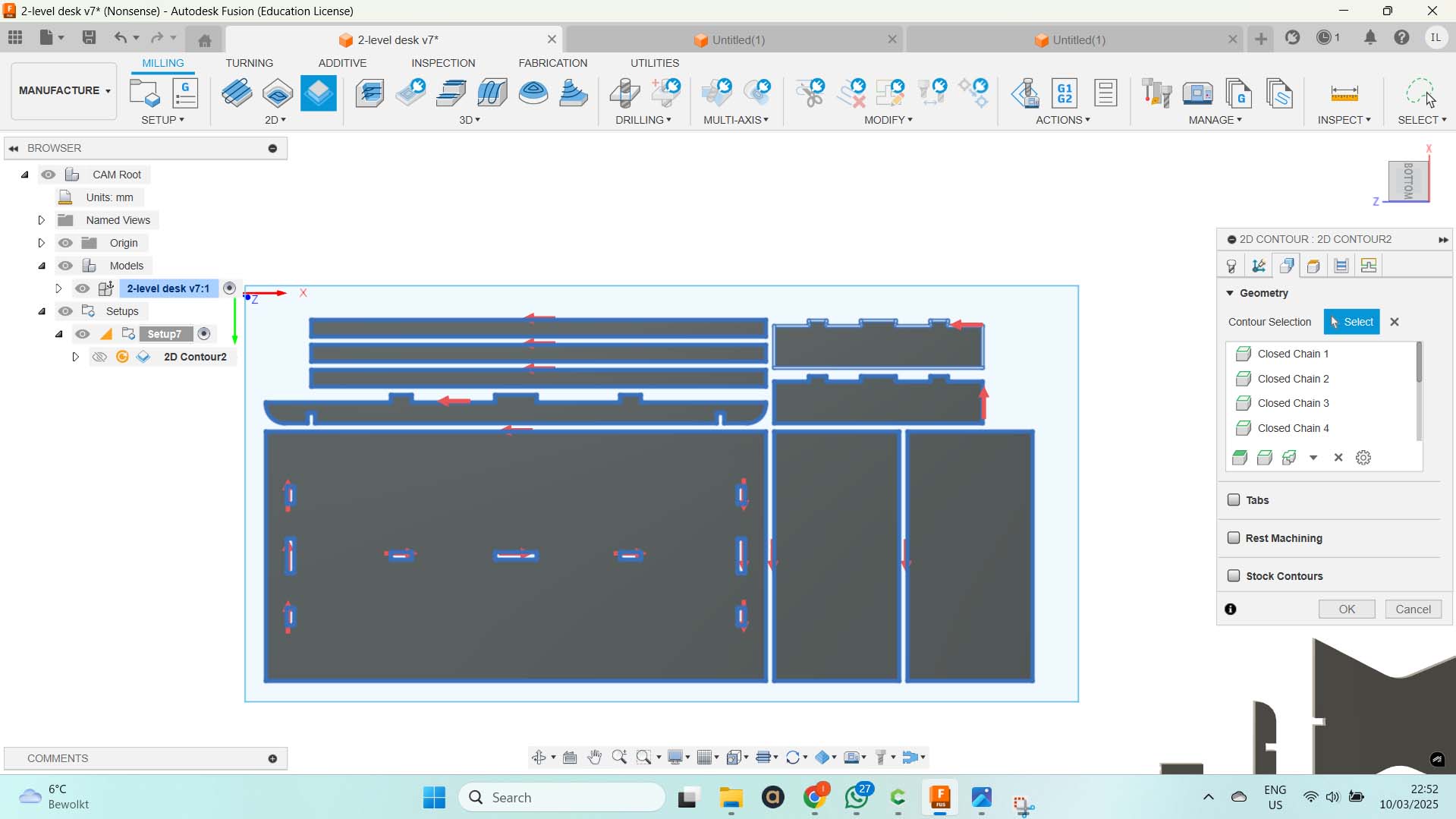
If you want to cut around a shape then 2D profile Toolpath is the way to go. Make sure the cut depth is the same as the tickness of your material. Choose to have the cut on the outside of the material if you are cutting out a piece.
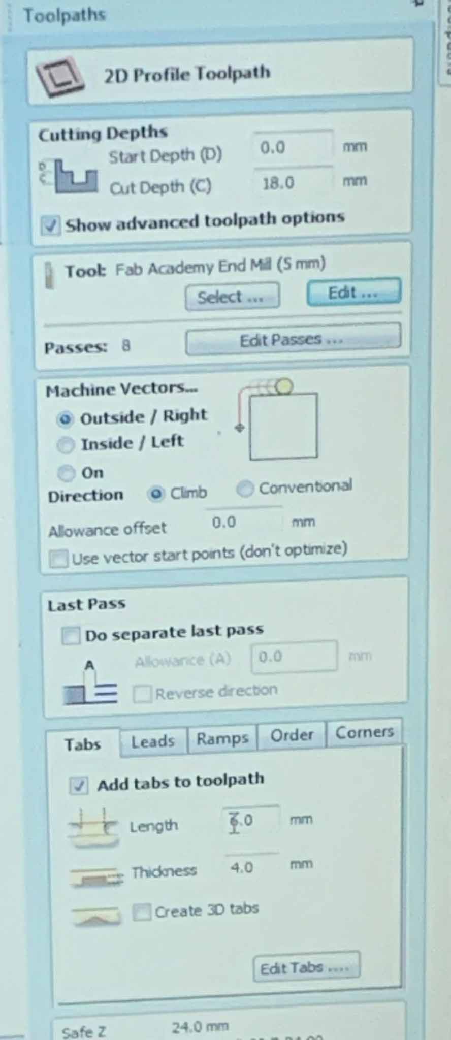
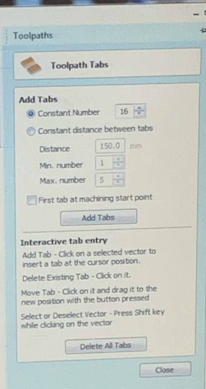
This is also where you add tabs. Tabs are there to keep teh material from moving. You want to avoid having tabs in corners or other places where it will be difficult to remove them.
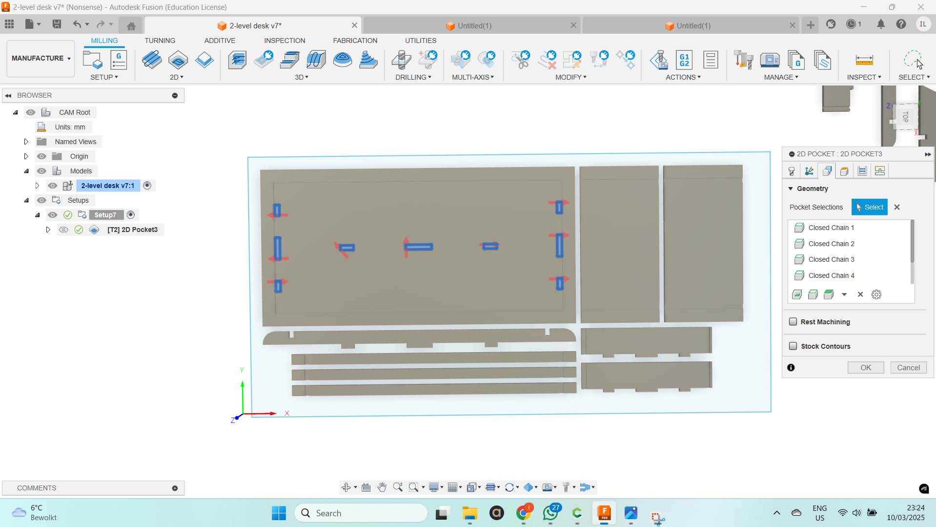
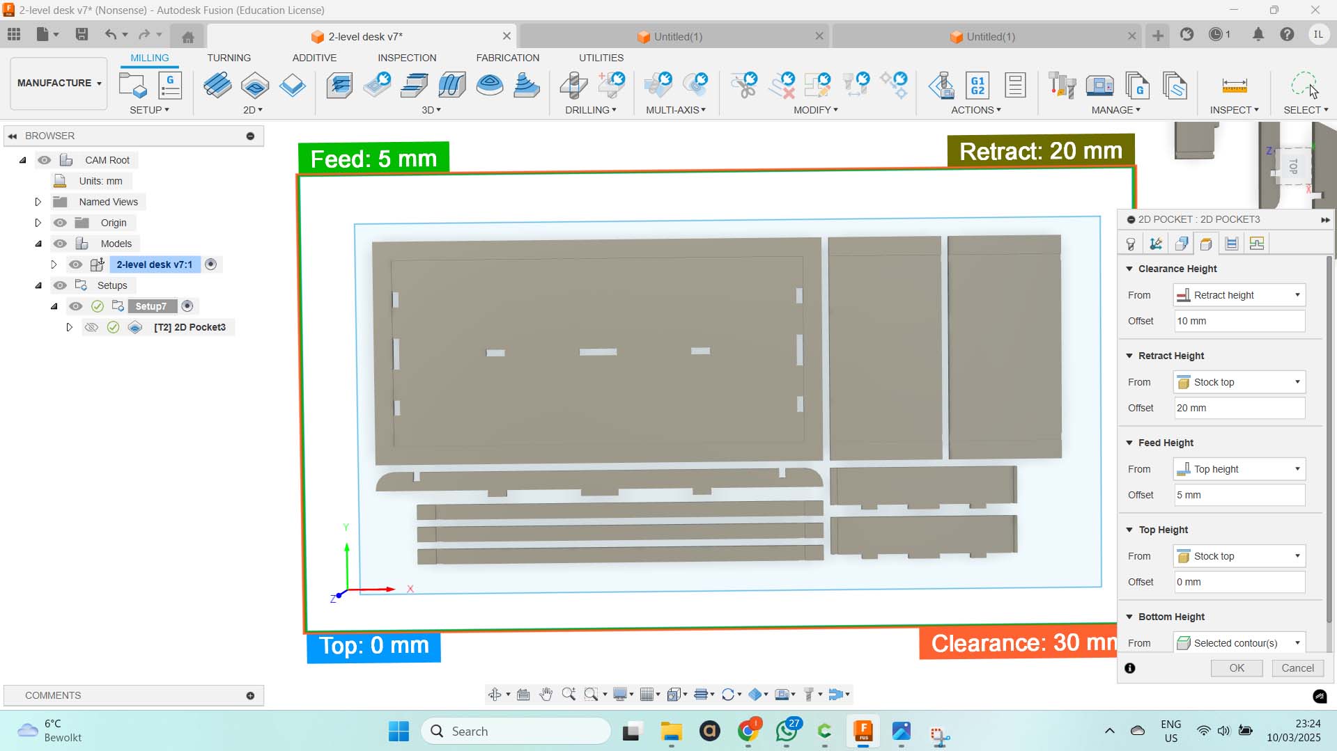
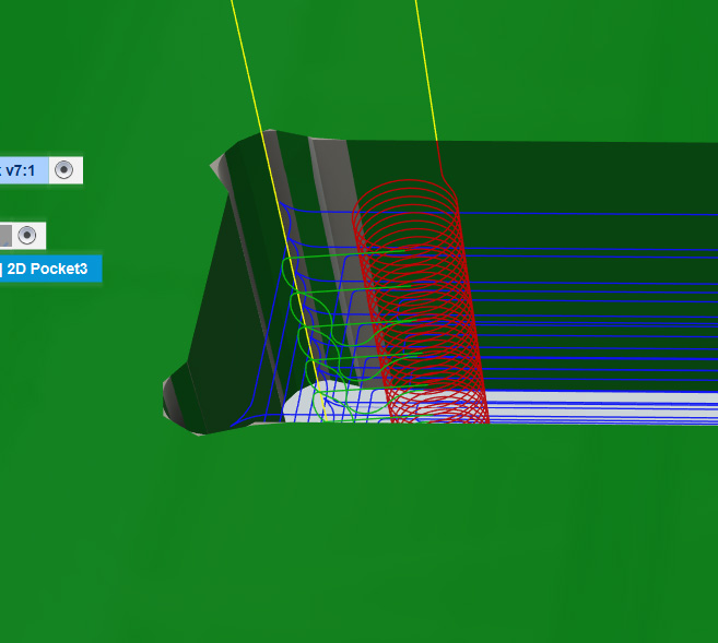
For pockets Pocket toolpath should be used. You then choose the 2 lines it should be milled in between and create a pocket in them. You can decide how deep it goes. We have declared every pass to be 2.5 mm deep. THat means that if the pocket should be 5 mm deep the milling will do 2 passes.
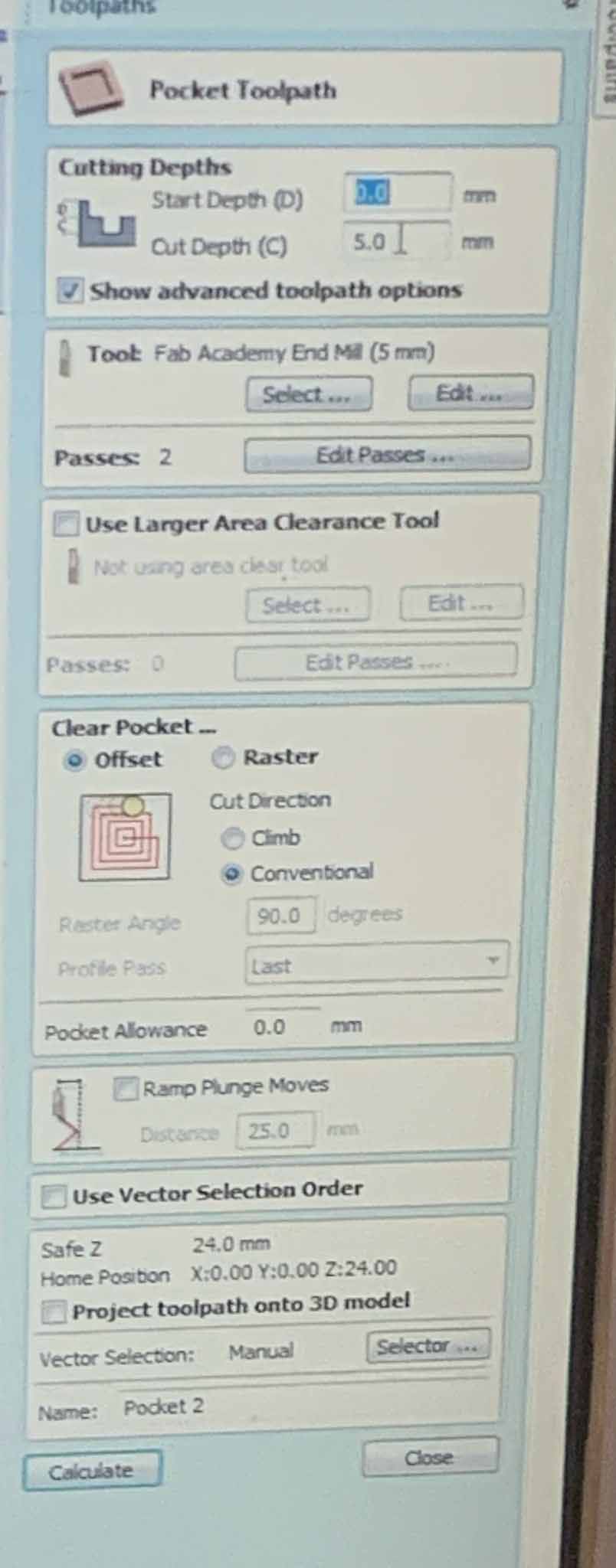
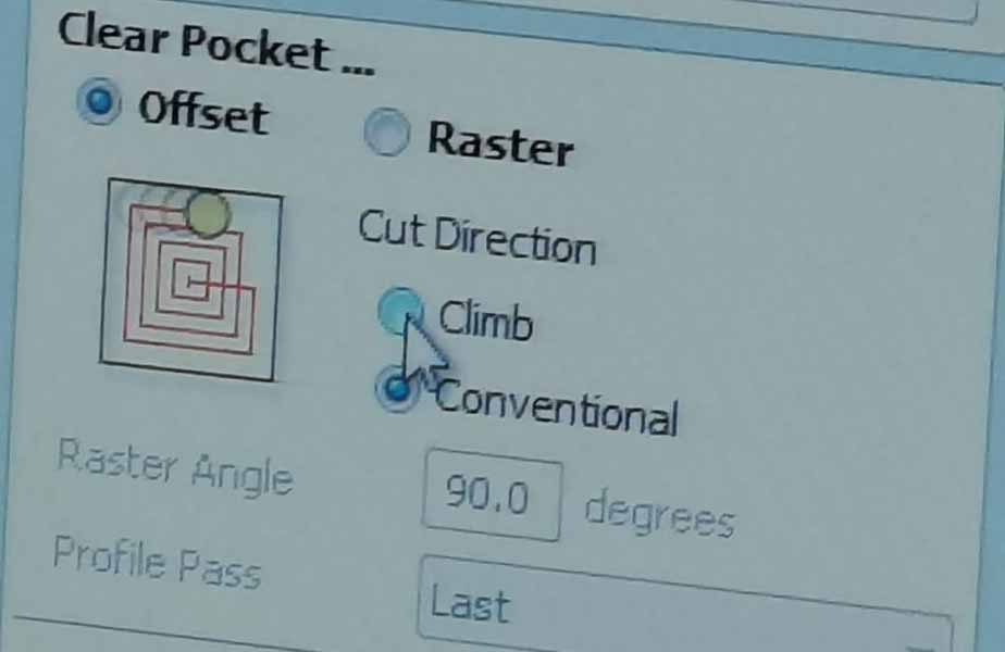
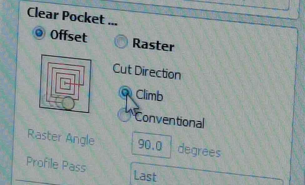
You can also choose between the modes climb and conventional. In climb the cutter rotates with the feed and in conventional the cutter rotates again the feed. Henk pointed out that when milling twith climb it also rotates the same way as what till loosen the nut. That is something to keep in mind.
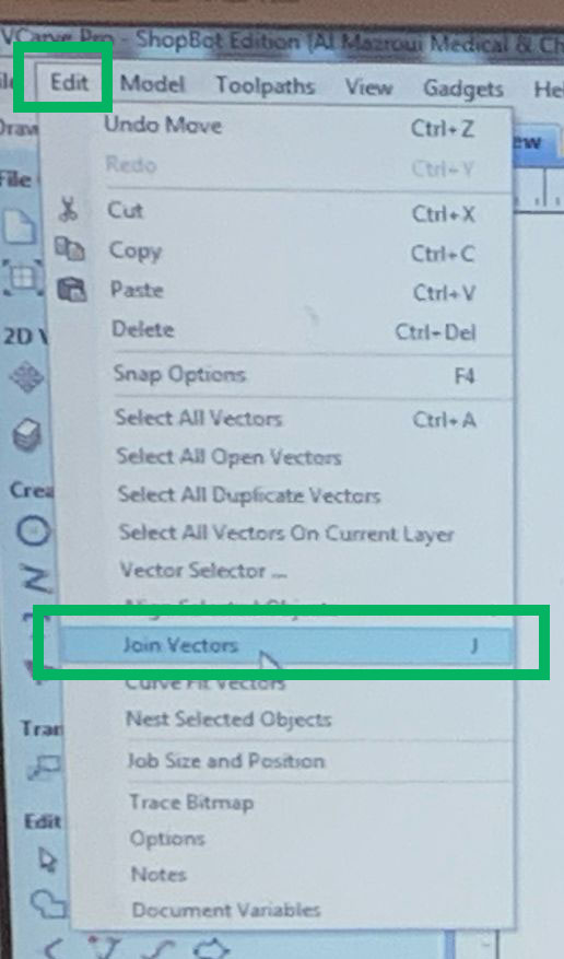
If you geometry for some reason is split inot multiple parts you can jopin them to fix the problem. Just hilight them, click Edit and join vectors.
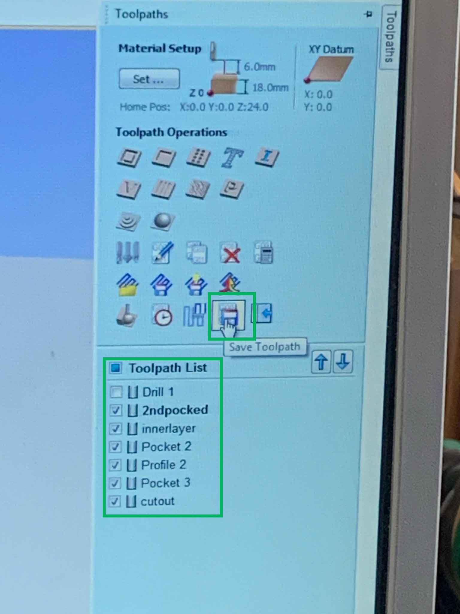
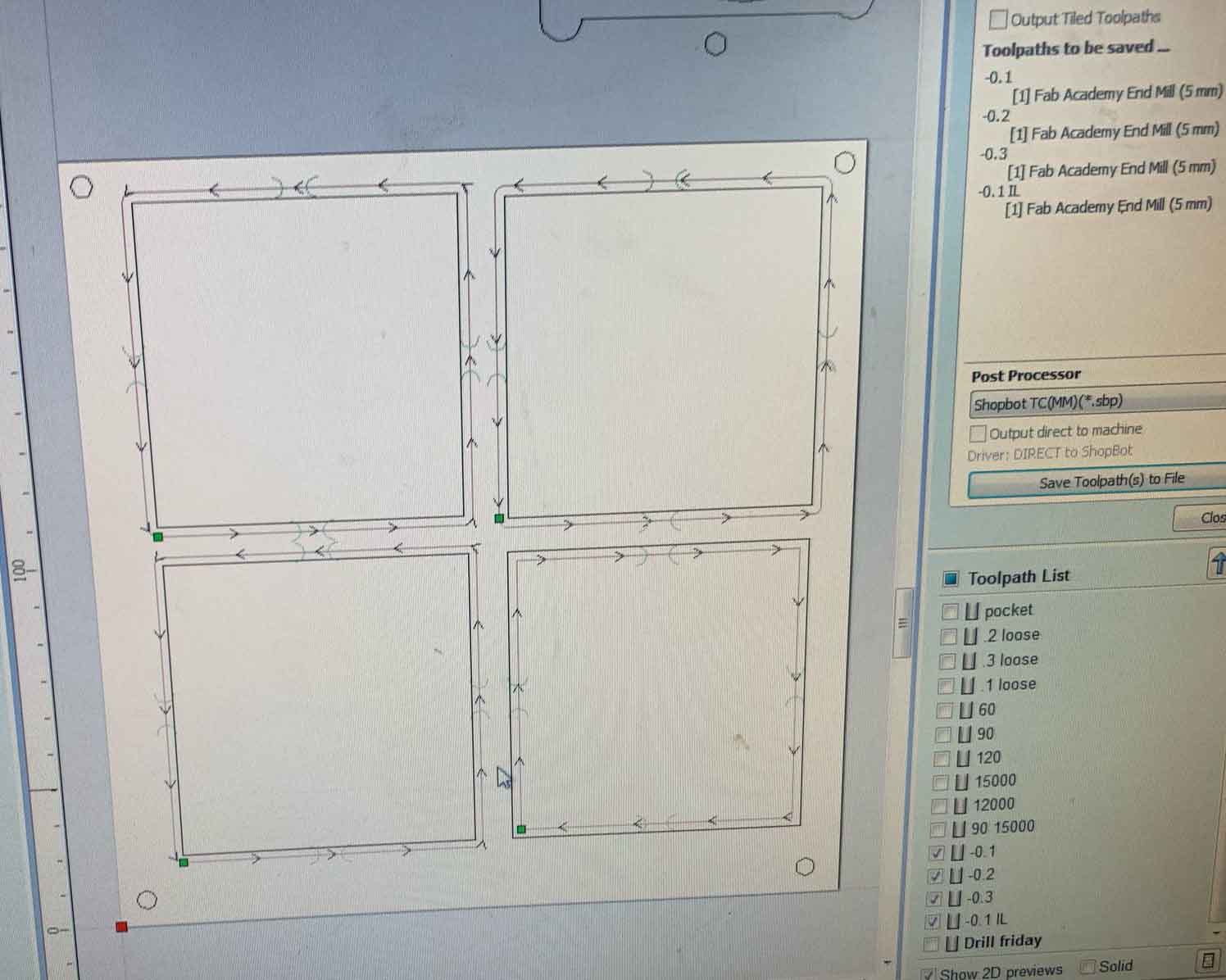
Before exporting the file check your settings and markings and put the drill layer first and the cutout layer last. THen export ONLY the drill layer. After this is exported uncheck the drill layer and export the rest. It is extremely important that the drill layer is not in the second layer as this will result in the ShopBot drilling into the screws creating sparks.
Milling
Now that the file is ready its time to satr milling. After making sure the surroundings are clear and you are wearing you safety glasses, turn the key next to the on switch. This will start the spindle. make sure the vacuum is also on.
On the box on the front you can adjust the spindle speed
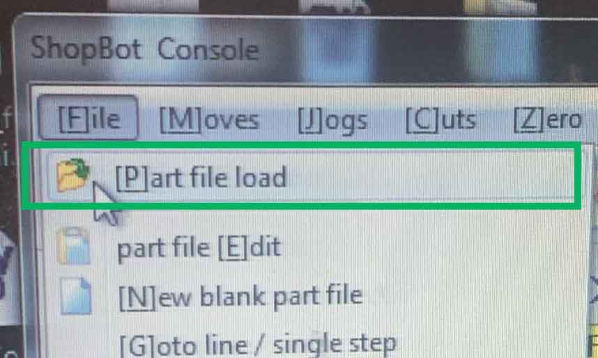
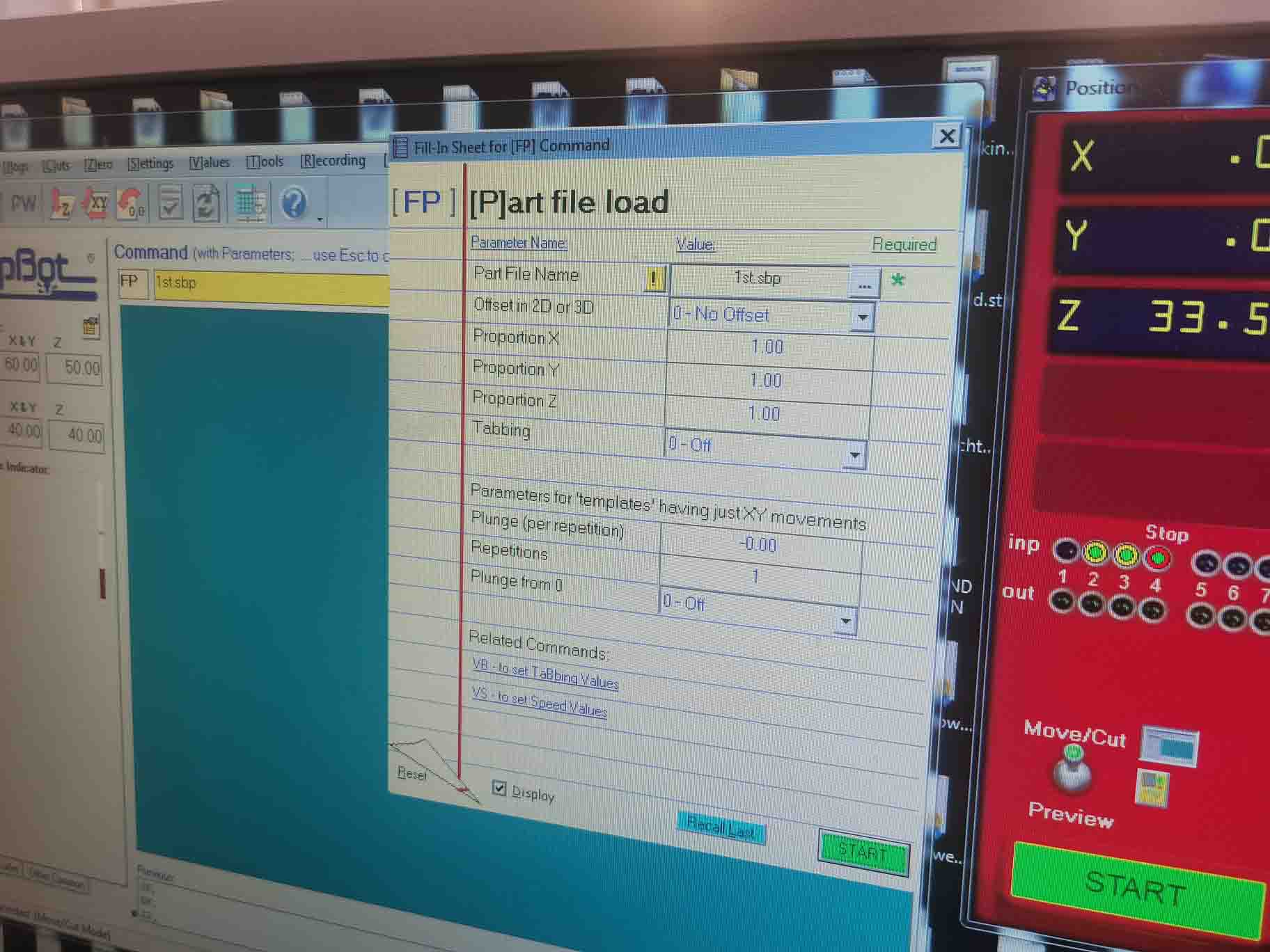
Import your file for the screws holes by clicking FIle and Part file load. make sure to move the x and y position to where you want your staring point to be.
When you click start the milling will begin.
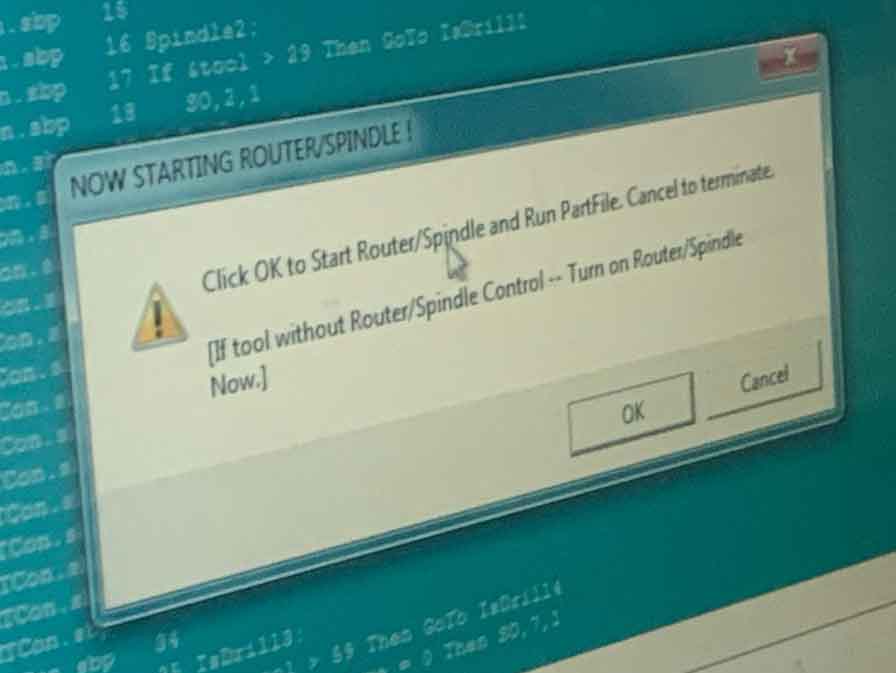
This warning will pop up. If you are sure everything is ready the you can click OK.
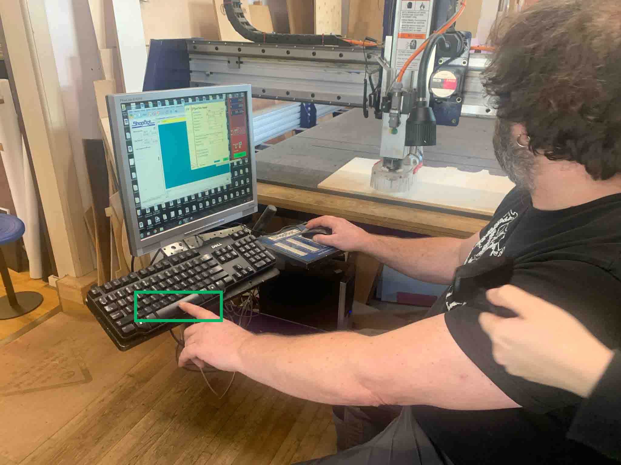
Make sure to keep a finger on the spacebar to be ready to pause if the spindel is in the air or hit the emergency stop if sparkrs should start flying.
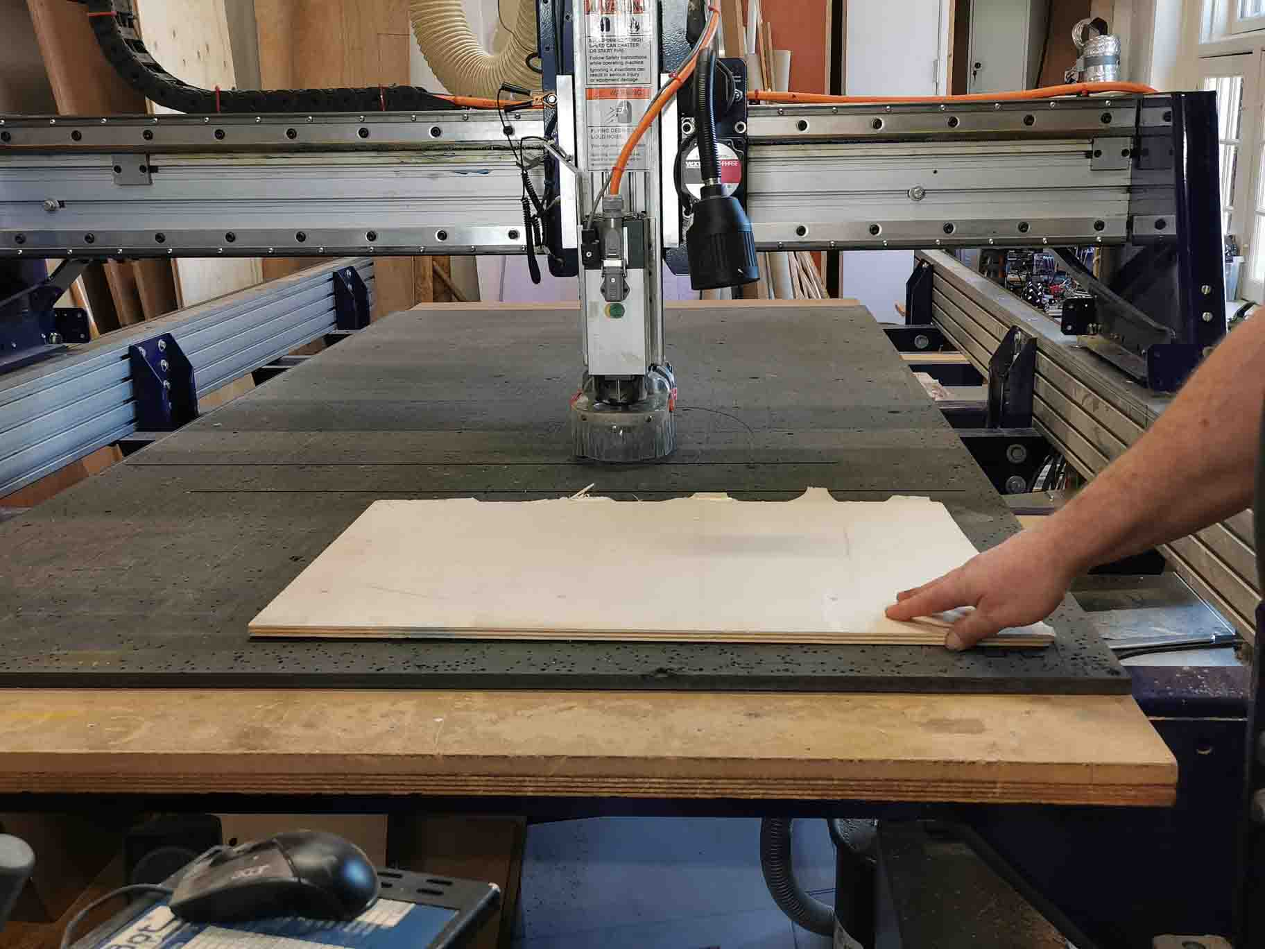
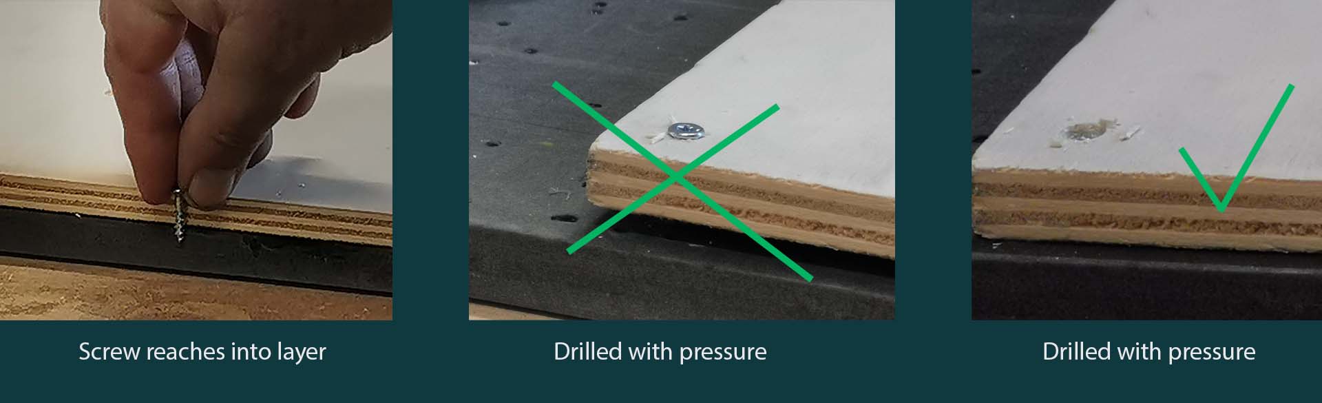
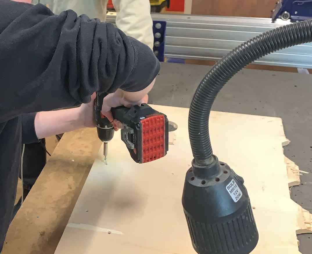
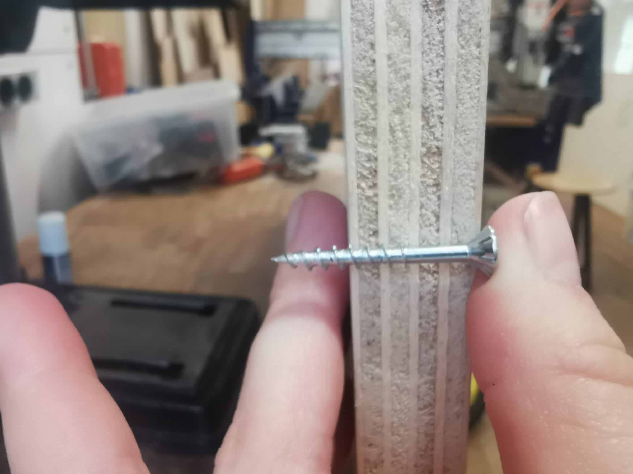
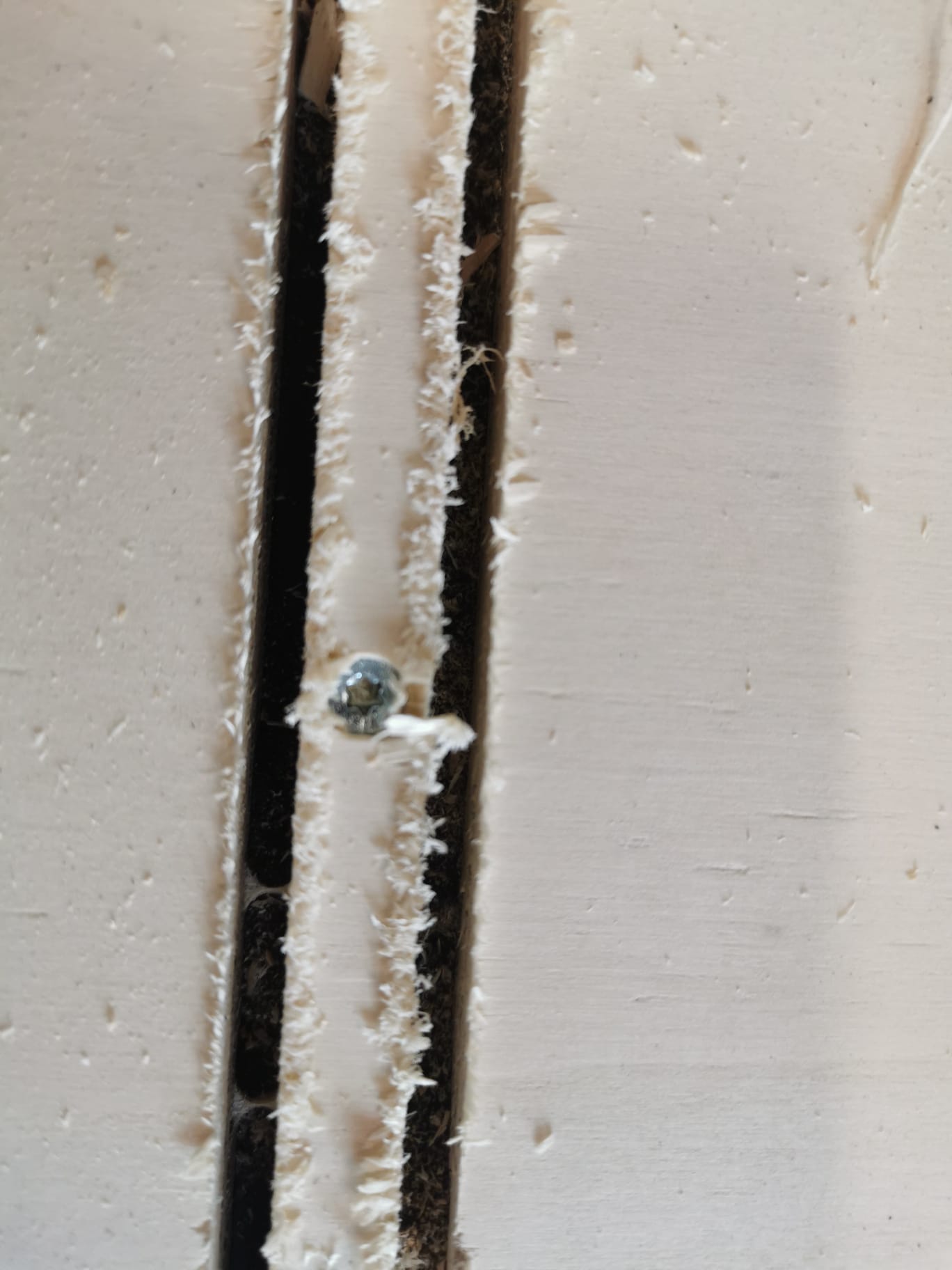
After the screw layer has been milled turn off the spindle, move the milling head out of the way and screw the plate into the sacrifisial layer using woodies from the vupboard in the back of the workshop.
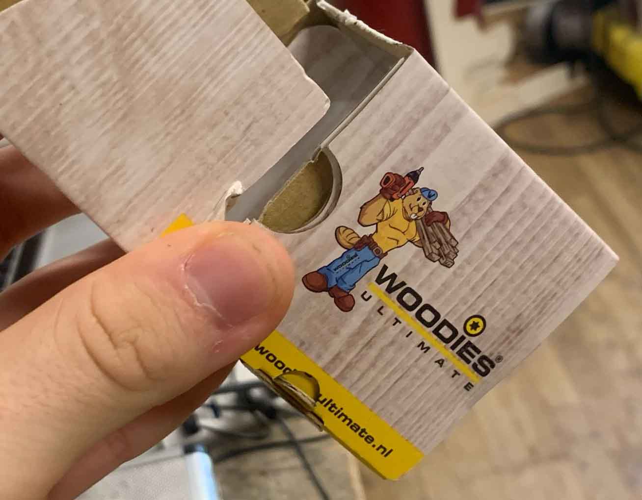
Make sure to press into the material, if not the plate will not be properly attached. See the image below:
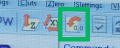
Click the home last job icon to go back to the x and y zero position for this project. and import your main file. Start up the spindle and press start again.
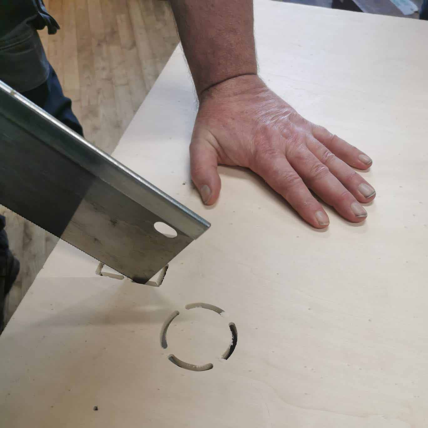
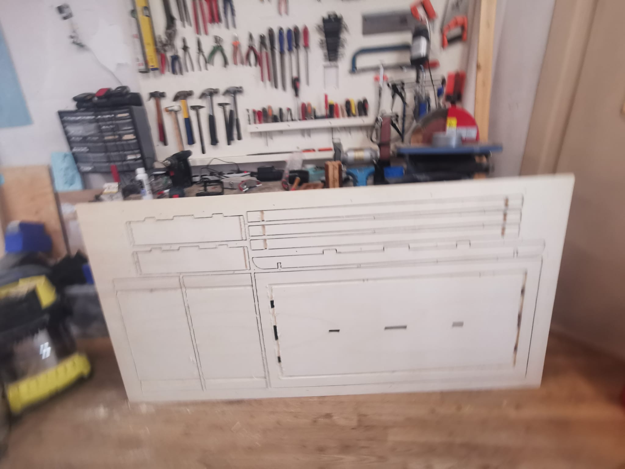
Here is the test milling Henk did to show us.
Removing the tabs: it is easier if you turn the material around.
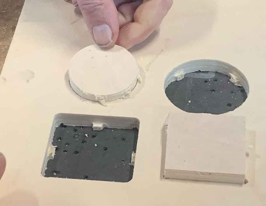
We tried to do a pressfit. With a hammer it was possible to get the pieces in but they cannot be separated. They were milled with no offset. It is too tight for if you want something to be dismantenable, we will therefore try to find out what the sweetspot is in our group assignment.
Group assignment
We fisrt made some shapes and put in the text settings in Vcarve.
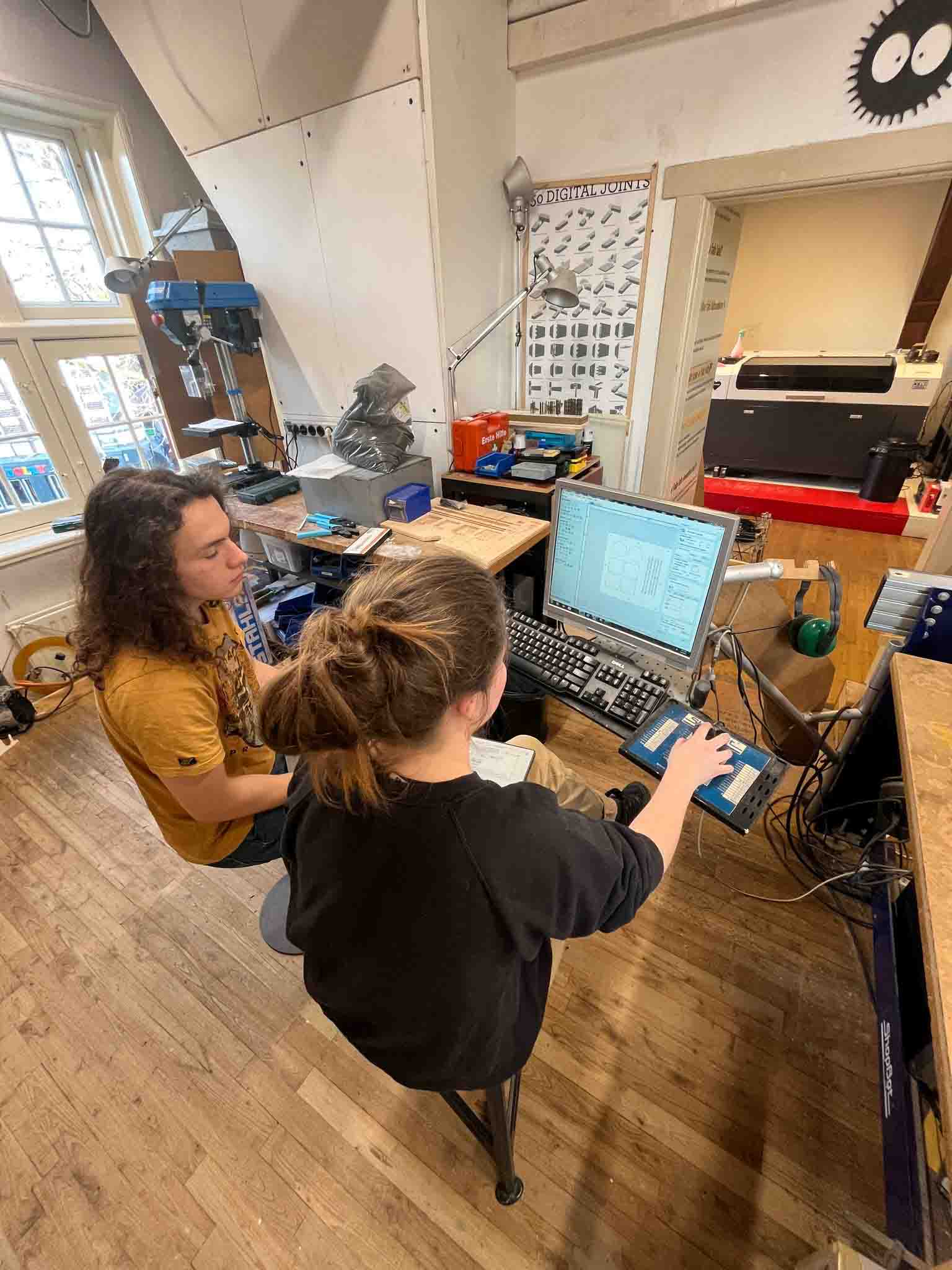
Since we had set up the machine earlier in the day with Henk we wen ahead and checked the area around, vacuumed the sacrfisal plate and leveled the Z axis. Then we placed the material on the table and setting the x and y axis. and after milling the markers for the screws whe attached the plate to the sacrifisal layer. and milled the next part.
First we ut the wrong depth for some of the pieces. We had left it at 2.5 mm rather then fill in the 12mm which was the thickness of the material. To fix this we changed the settings in VCarve and re-cut those pieces before moving the material.
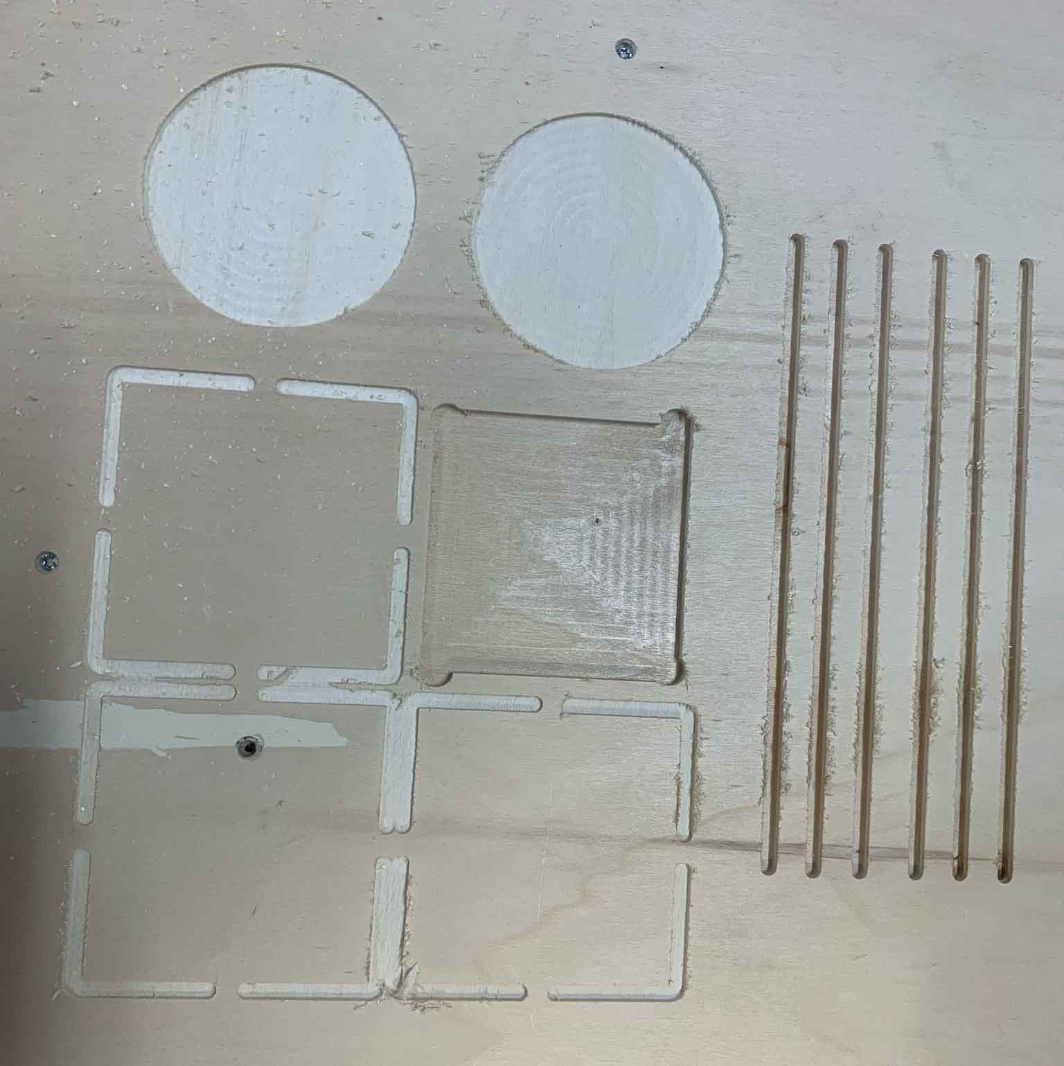
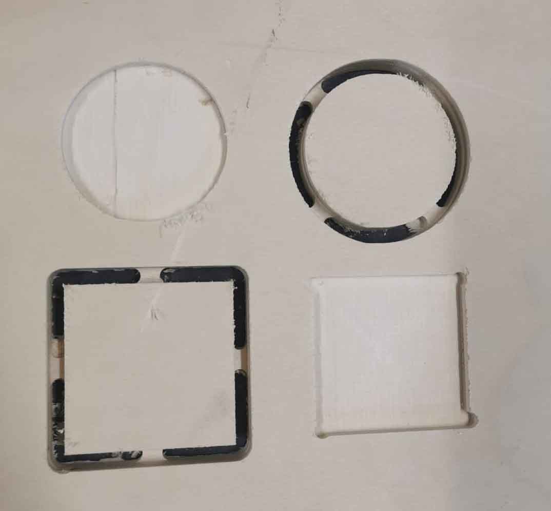
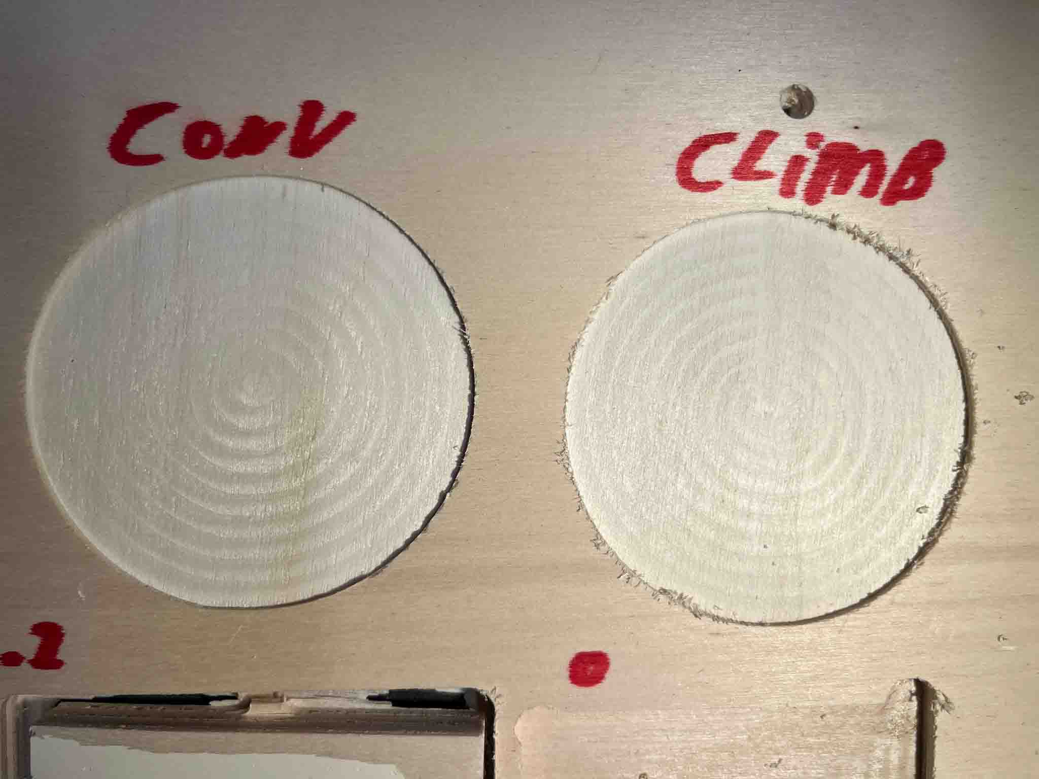
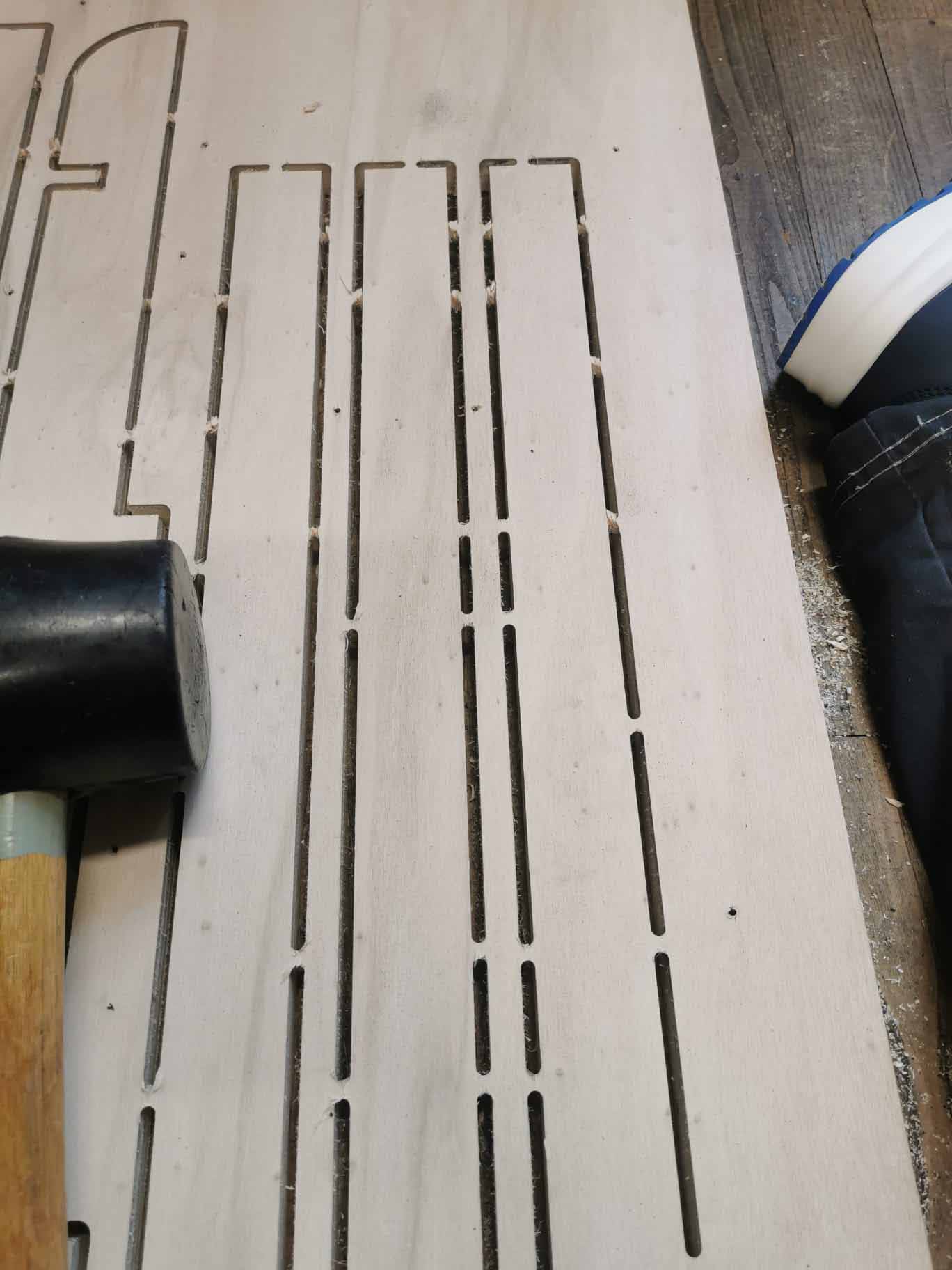
We made a lot of mistakes in our first test. TThe only part that is usable for the tests we wanted to do are the climb and conventional cuts. As you can see under using climb resulted in a messier edge then conventional milling.
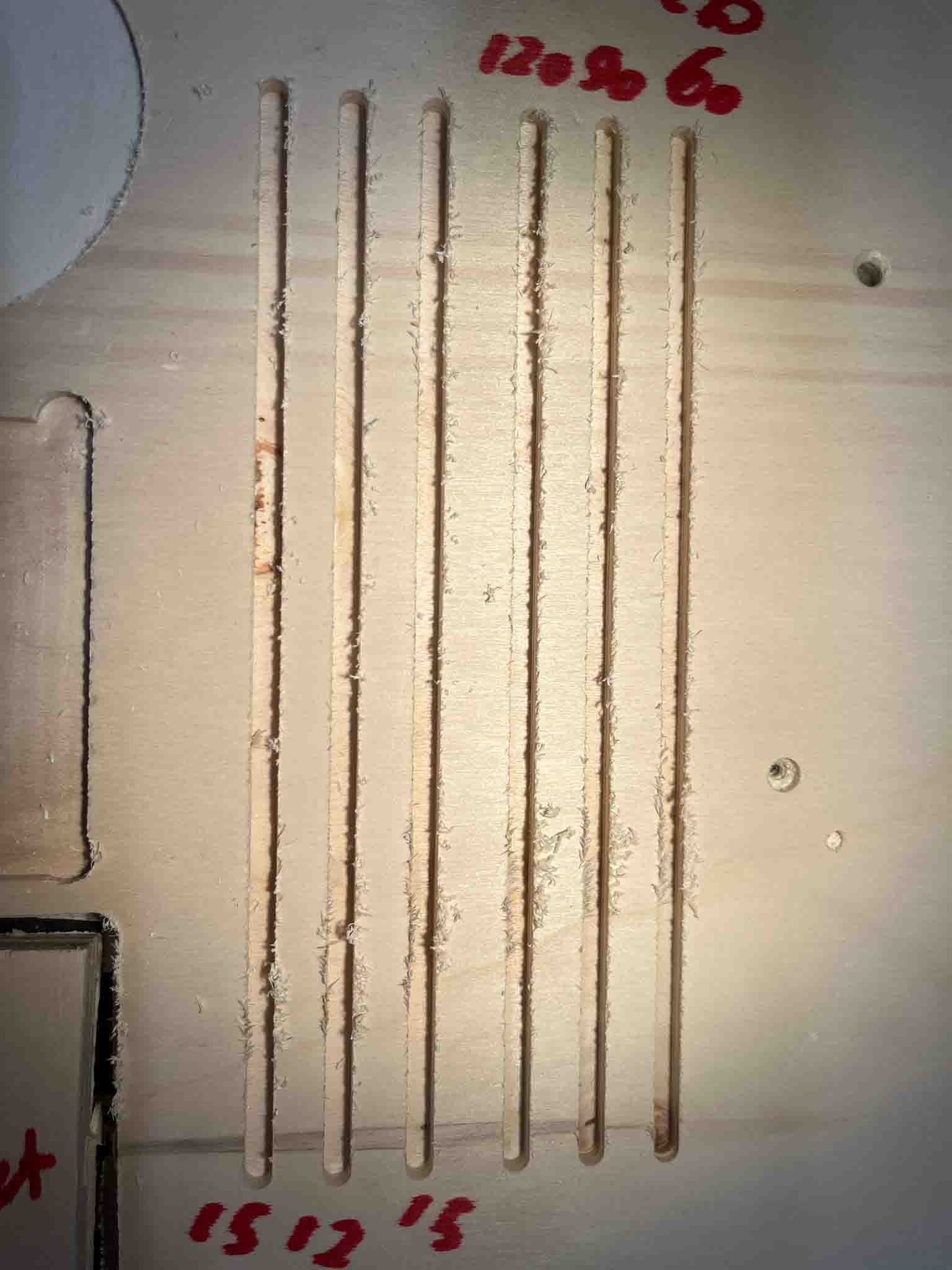
For the line tests we tested feedrates of 60, 90 and 120 and rotational speeds of 18000, 15000 and 12000. + an extra line of 15000 at 90 feedrate. Our mistake here is that we are cutting against the grain so it is hard to tell how the cut is as they all look messy. Will defintley think about that next time im milling!
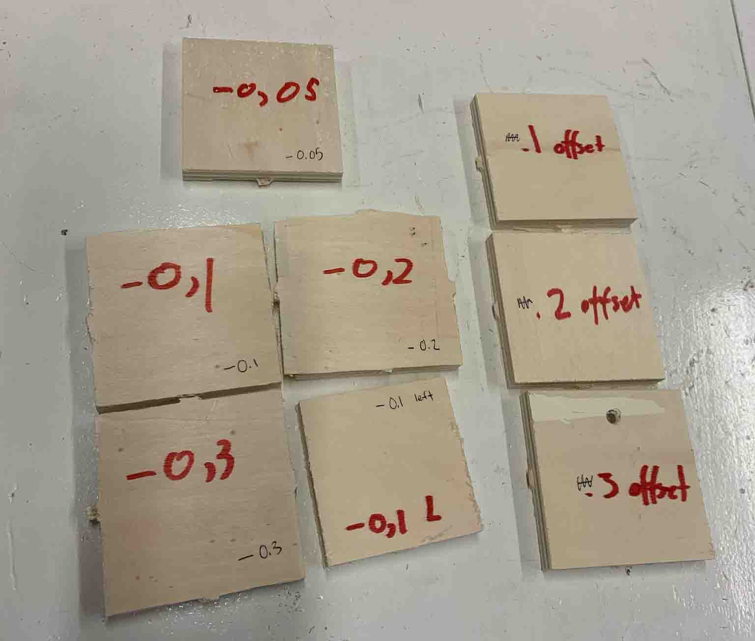
The next day Sam and Dylan went in to try the last test again. We had wanted to test the offset, but had offset from the outside and not inwards. All our pieces were therefore too big rather then getting smaller as we intended. They wen in and redid the milling but with -.005, -.1, -.2 and -.3.
From what tehy told be -.1 was a good fit, but mabye slightly loos and therefore -0.05 is seen as the sweetspot for a snapfit construction.
my Idea :
When deciding what to make this week I made a list of what could be nice to have at home and then threw in some requirements for each of them to give me some guidance later on. Ever idea got written down, even if the were not plausable.

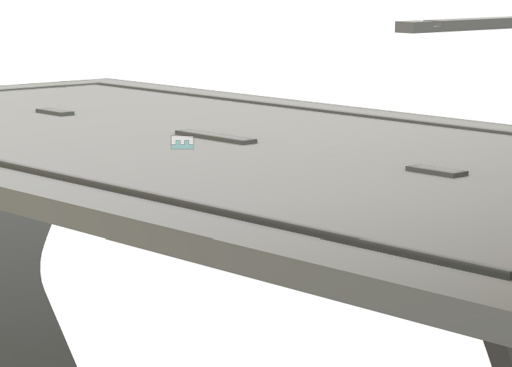
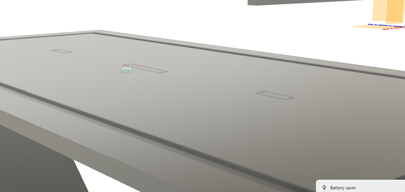
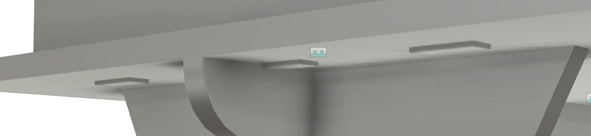
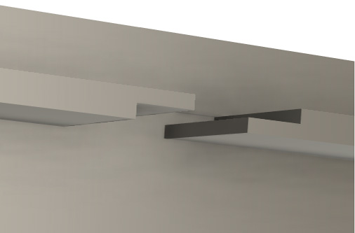
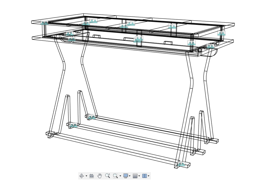
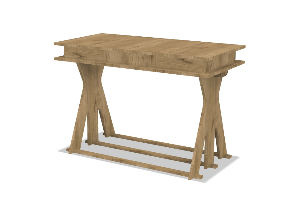
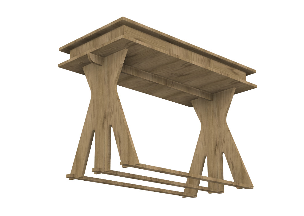
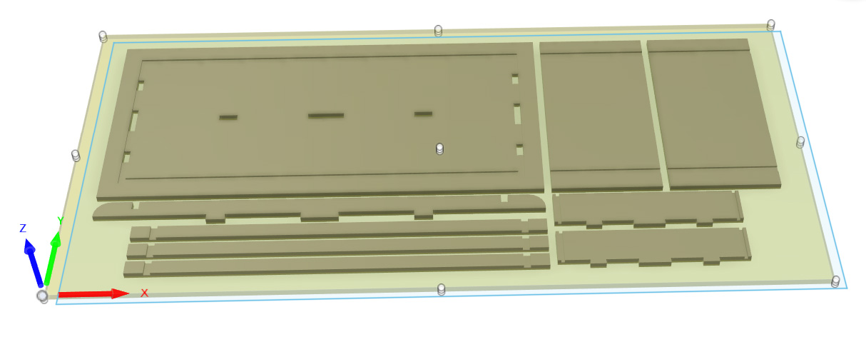
I decided to make a desk with a removable top. The 2 levels should be at a hight where the lover one fits me well and the top one my partner. The main goal of this is that I can just add the top parts back on when I am done working so that there is a clean desk, no one gets annoyed and the cats don't nibble on anything important. Moving on to sketching possible top solutions.
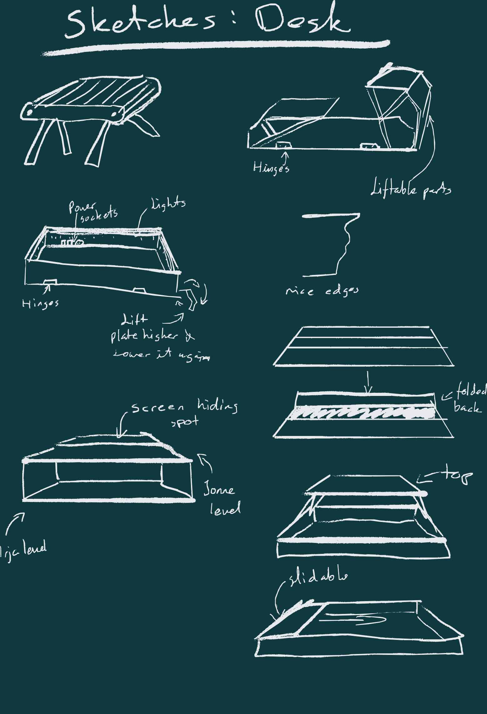
In the end I liked the idea of the slidable top parts the most. I ended up changing it a bit, but the plan was tha


 Images of sketches from
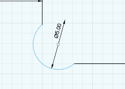
dogbones in fusion https://github.com/tapnair/Dogbone
Images of sketches from
dogbones in fusion https://github.com/tapnair/Dogbone
https://www.youtube.com/watch?v=veXvbGSDtPk follow this video
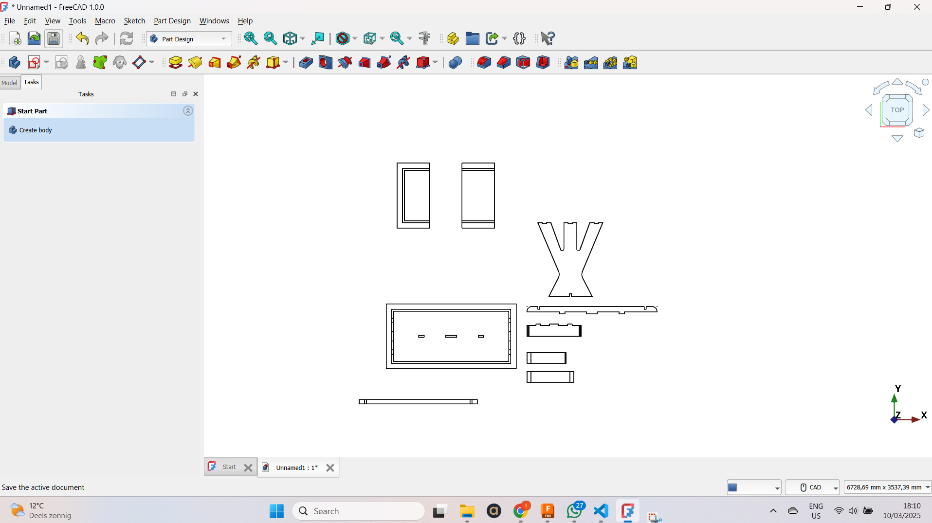
Freecad:toolpaths: https://blog.freecad.org/2023/11/24/tutorial-getting-started-with-the-path-workbench-part-one/
Carbine:create: https://carbide3d.com/carbidecreate/download/
good tutorial : https://www.youtube.com/watch?v=_G-0i8BFEFs&t=223s
Nice resources
opendesk.cc chairigami japanese wood joints: https://www.thingiverse.com/thing:169723 Vcarve How to use the ShopBot How to use the ShopBot