Electronics design
Intro to electronics by Erwin
On Thursday this week Erwin gave us an intro to electronics. It was quite a lot and I'm going to try to summarize it as best I can. First we start with a few concepts that are at the basis of it all: circuit, voltage, current and power.
In order for there to be electronics we need a circuit, and a circuit is a closed loop where electrons can flow.

Voltage (V or Volt) is the difference in electrical potential between points, and the sum of all the voltages in the loop are always 0.
Current (I or Ampere) is the amount of flowing electrons in the unit. and the sum of all current in a node is also always 0.
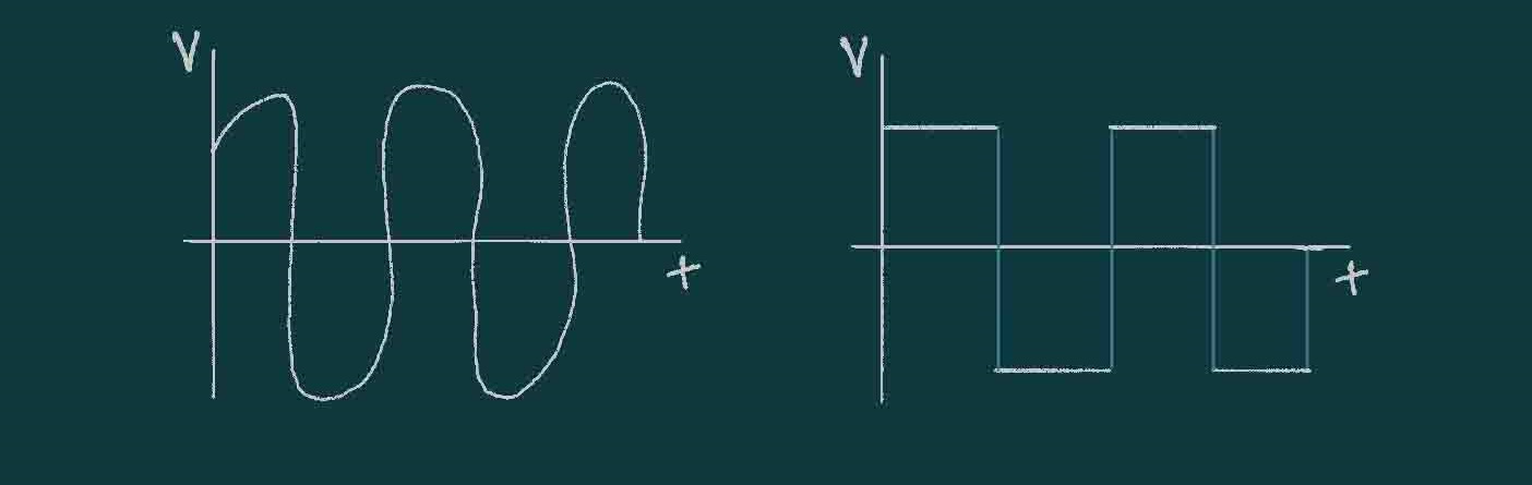
In a direct current (DC) the electrons always flow in the same direction.
In an alternating current the electrons keep switching direction, the Voltage also switches.
Power (P, Watt) is the voltage * current. Energy is Power * time = (for instance:) kWh
Components
Now onto some key components:
Resistors (R,Ω, Ohm)

Resistors are current limiters and are calculated by R = V / I, and are one of the most important components we have. THey have no polarity, meaning that it does not matter what what it is placed.
Capacitors (C, Farad)
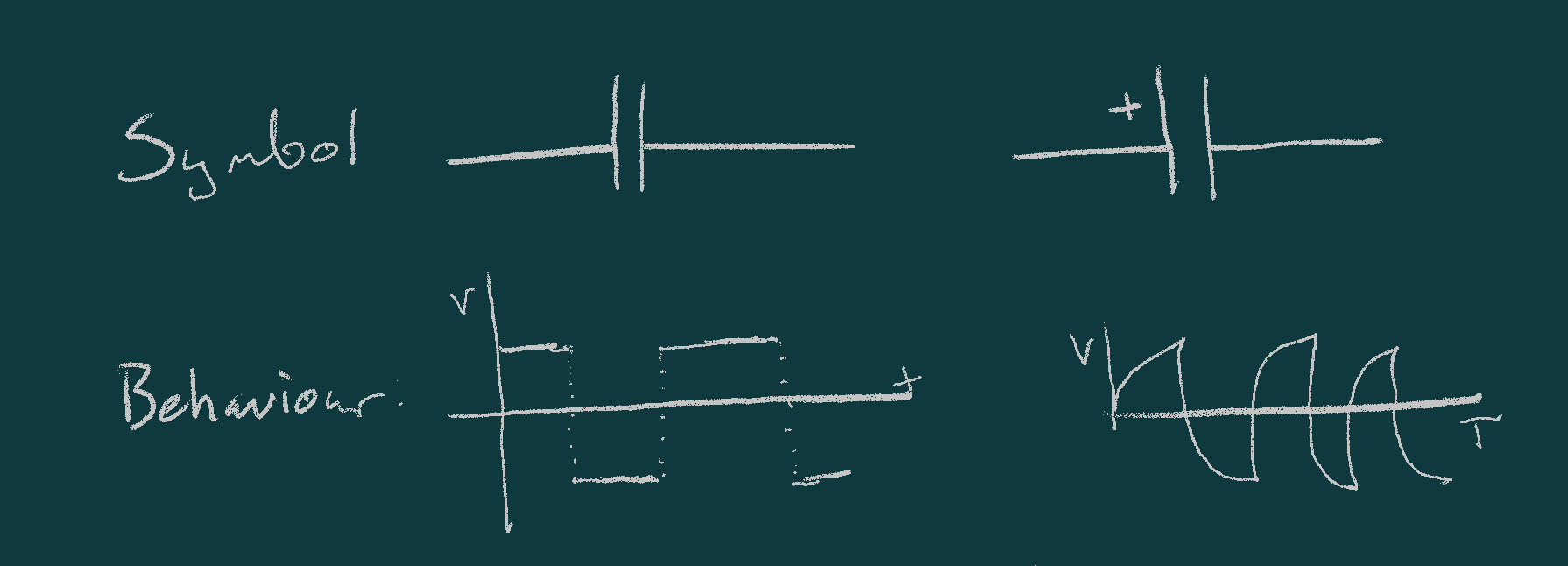
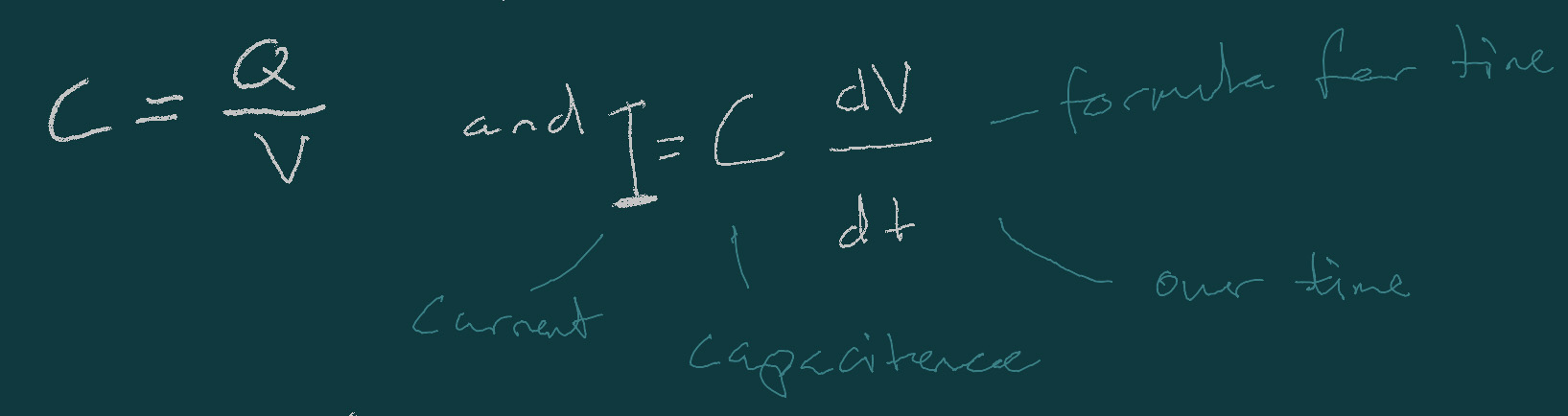
A capacitor is a storage tank for electric fields (charge).And is calculated by C = Q/V or I = C dV/dt. Capacitors can be both unpolarized (ceramic, tantalum) and polarized (electrolytic).
Diode / LED (D)

Diodes are a one-way valve for electrons. LEDs are Light Emitting Diodes in which the color depends on the elements used. These can also be light sensitive. It is important to always add a resistor to an LED to limit the current.
Coil (L, Henry)

A coil is a storage tank for magnetic fields and is calculated with L = V / dI/dt. It is used in relays and motors. It uses a flyback diode to release the charge over time if not in use.
Transistor (Q)
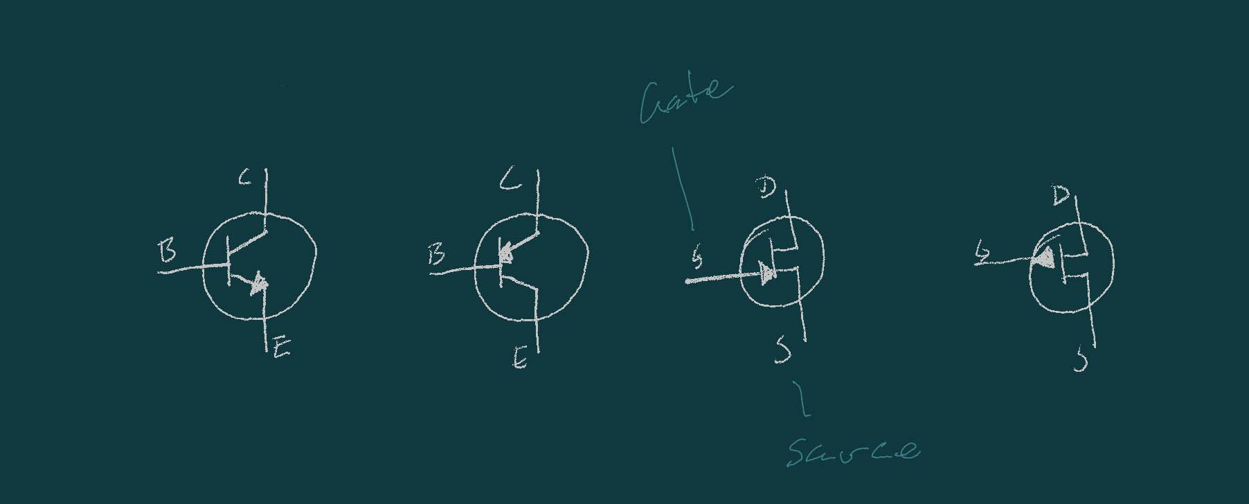
A transistor is an amplifier and/or switch.
A bipolar transistor can amplify a small current into a large current. TO calculat this we use the formula Ic = β * Ib where β = amplification factor.
A MOSFET a can use a small voltage to drive a larger current.
Microcontrollers (U, IC)
Microcontrollers are integrated circuits buildt from transistors (mosfets). They are programmable devices with inputs, outputs, memory and calculation engine (ALU), Digital inputs and outputs (I/O), Analog inputs (ADC), Analog outputs (DAC) and Digital interfaces (serial, i2c, spi, twi, updi, jtag, ...). And they are contrlled by registers.
We covered this more earlier in the course. And there are some great presentations on Erwin and Leos documentation pages.
Moving on to measuring devices:
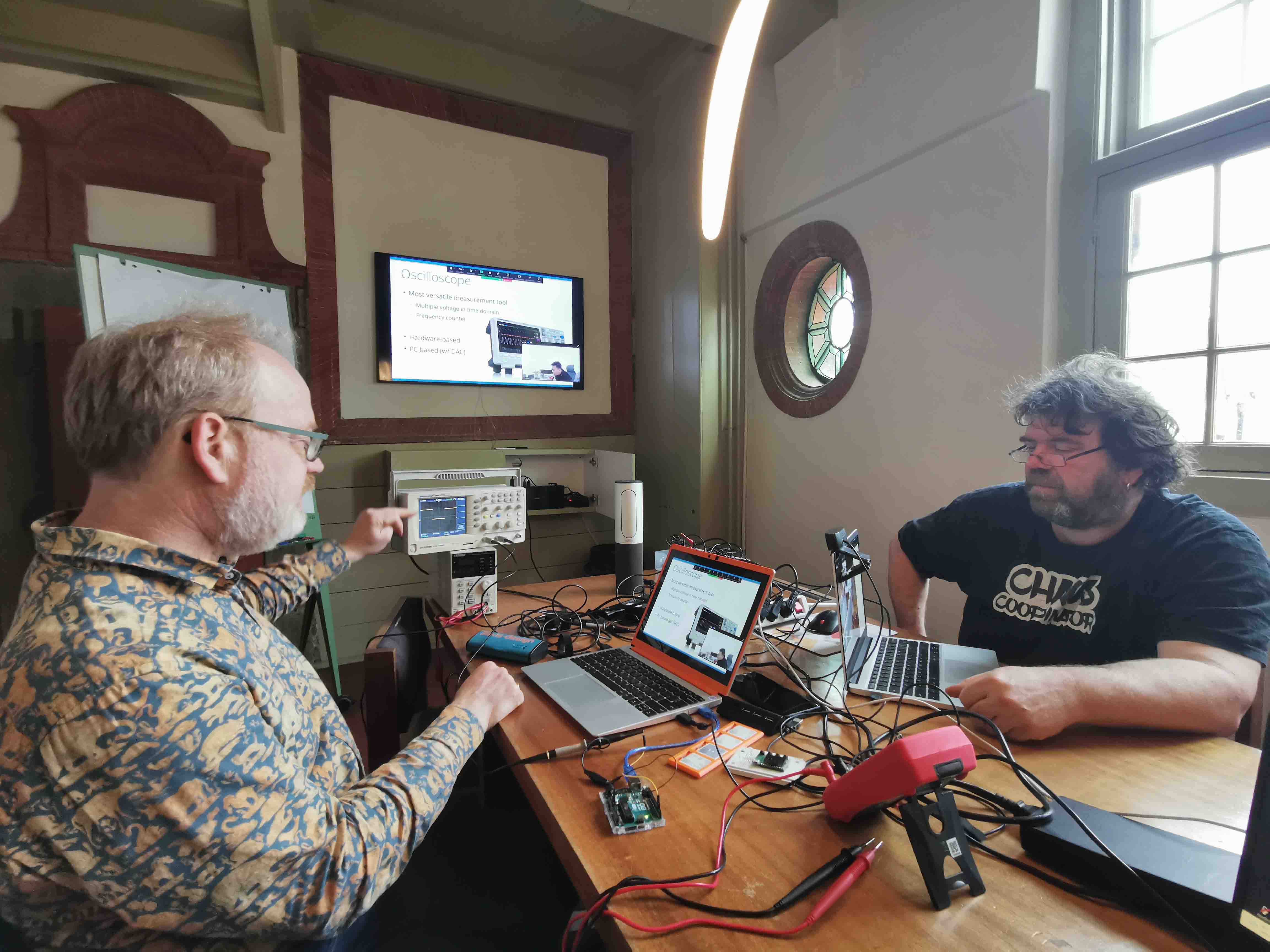
Osciloscope
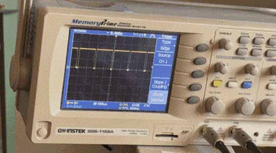
An oscilloscope is the most versatile measurement tool. It can be used when you don't know much about the circuit. An oscilloscope can be used to measure Voltage over Time. Erwin used it to show us how dimming an LED works with a PWM signal.
It can be confusing when the measurements are moving across teh screen so by using the trigger it is possible to sync up when the measurement starts to create a clear view of the changes in Voltage.
It is alos possible to set a minimum amount of Voltage to get measures. This is done with line. Every measurement under the line is then ignored.
An ocilloscope can be both hardware based as seen in the image above and screen based. Then it is a smaller piece of equipment that gets hooked up to a screen.
Multimeter
A multimeter can be used to check voltage, resistor, if parts on the board are connected. I have used it mostly for troubleshooting when something is not working in my circuit. One major difference between this and an oscillosocpe is that a multimeter does not show change over time.
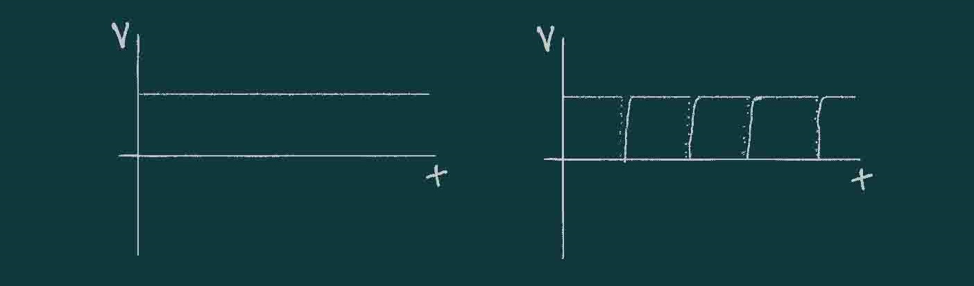
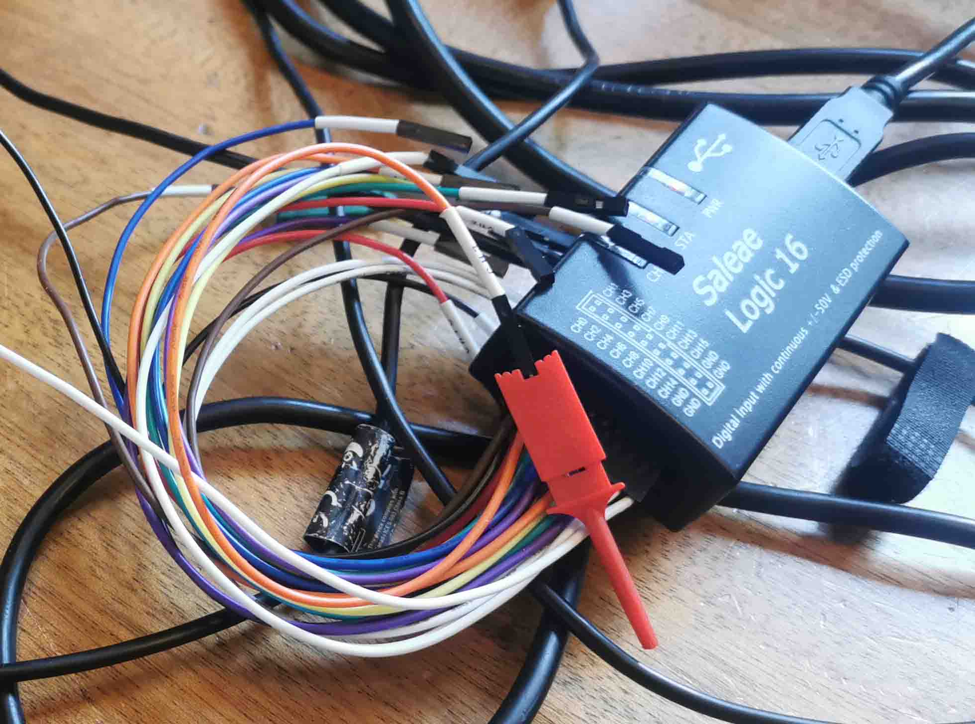
Logic analyser
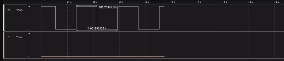
A logic analyser is a sort of oscilloscope for digital signals. it is useful in showing the relation between multiple signals. It can be used for decoding digital protocols. It measures digital signals in ON/OFF.
Here is a screenshot of what the digital screen looks like:
KiCAD Scchematic
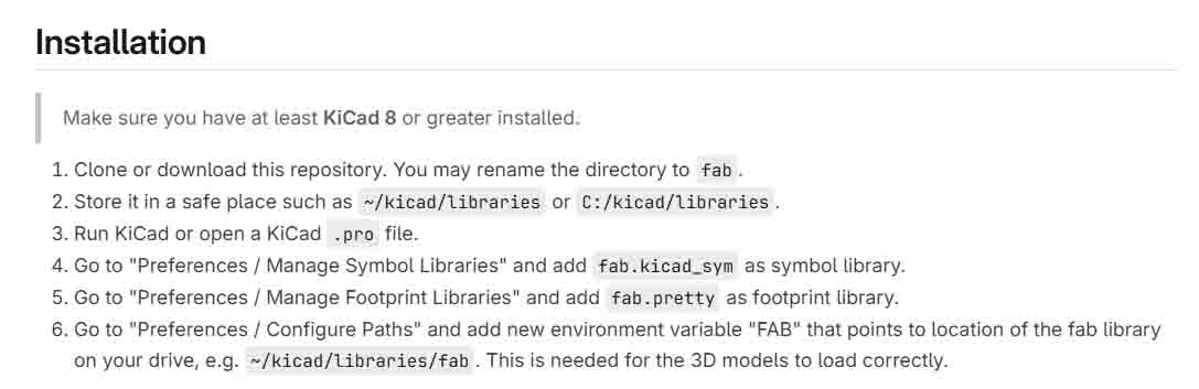
To produce our electronic boards we are using KiCad. In KiCad it is a Fab academy library that can be installed by cloning this repository. This repository contains all the parts that exist in the Fab inventory. A guide for installation can be followed here:
After installing the library we created a new project. KiCad then provides a schimatic and a PCB file. In the schematic file new components can be added by presing A.
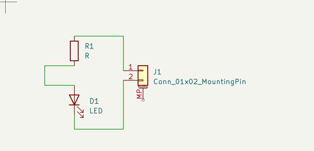
We made a very simple circuit consisting of an LED, resistor and a mounting pin:
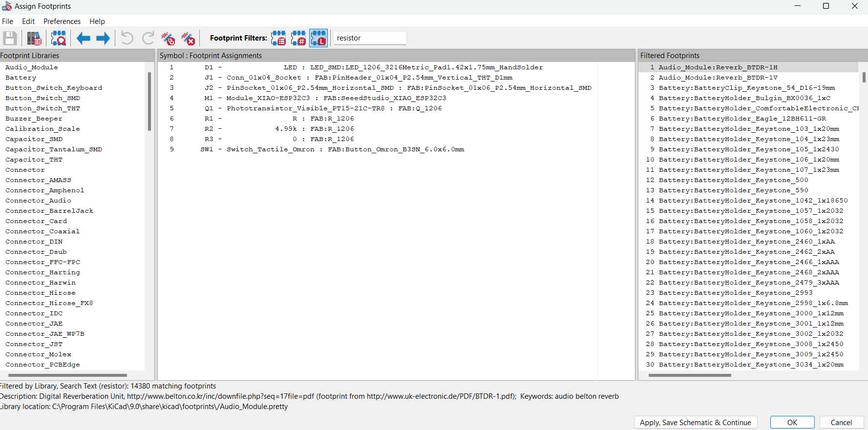
Before moving on each componen needs to be assigned a footprint.
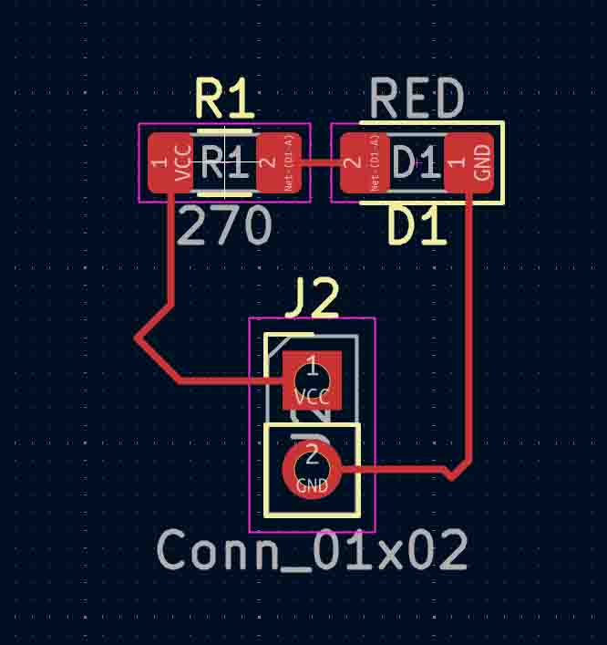
Then moved on to the PCB file, clicked update PCB from schematic and routed the components together.
For when later it is good to keep in mind that at Waag we have some 2 layer circuit boards so we wan also route some of it on the backside of the board.
Some good shortcuts:
| Button | Function |
|---|---|
| Alt 3 | low-medium speed |
| A | Add component |
| G | Drag component |
| R | Rotate |
| Del | Delete item |
We also need to set the design rules:
Milling bits: Normally: 0.4 mm smallest: 0.1 mm, but this is hard to debug Plot --> SVG --> check layers: F.CU (front copper layer), Edge.Cuts x2 --> uncheck sheet
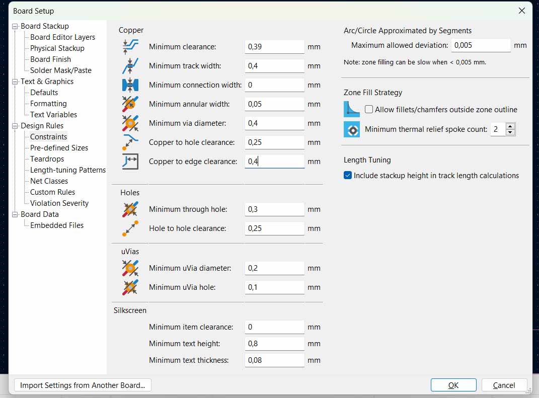
Design rules we will use: Minimum clearance: 0.4 mm // same as milling bit Minimum track width: 0.39 mm Min. connection width: // provided by producers, based on machine and mill Min. annular width: .1mm min. via diameter: .6 and .8 an 1 mm (checks this, what we have at Waag) // size of circle going through from top to bottom layer copper to hole clearance: .25 mm COpper to edge clearance: 1mm + // no copper on edge, will be removed
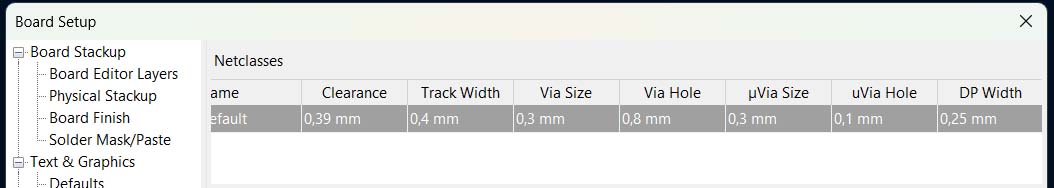
Net classes: clearance .4 mm track width: .39 via hole: .3
Design rule checker: THis is used at the end to see if the circuit would be alright. Run DRC: - tells the errors.
My own board
For my own board I will design a board that can detect and display the humidity in the room. In addition to this there were a few requirements to the assignment. I also needed to include external: a pushbutton, an LED and either a SPEAKER 8OHM 250MW or a SENSOR PHOTO 940NM TOP VIEW 1206 with all the necessary extra resistors and so on.
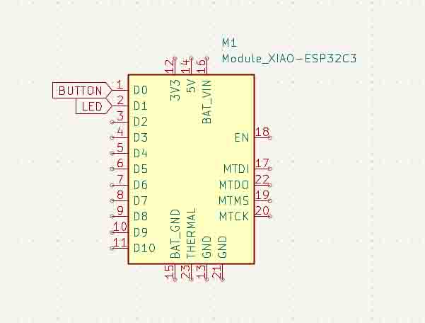
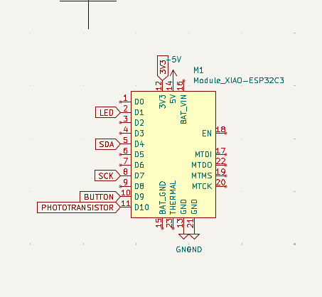
I star by adding a XIAOESP32-C3 board to the schematic by pressing A and choosing the board from the FAB library.
How to power the board:
Using the 5V pin the start up guide from XIAO states that 5V - This is 5v out from the USB port. You can also use this as a voltage input but you must have some sort of diode (schottky, signal, power) between your external power source and this pin with anode to battery, cathode to 5V pin.
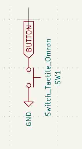
button
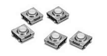
I will be using a Sealed Tactile Switch
 '
'
I am using labels to connect the button to the pins on the XIAO board in the schematic.
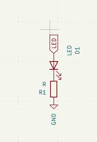
LED
Next up is to connect an LED. I know from earlier that an LED needs a resistor so I add this and attach the labels for LED and a GND.
Phototransister
I chose to work witht the phototransistor rather then the speaker.
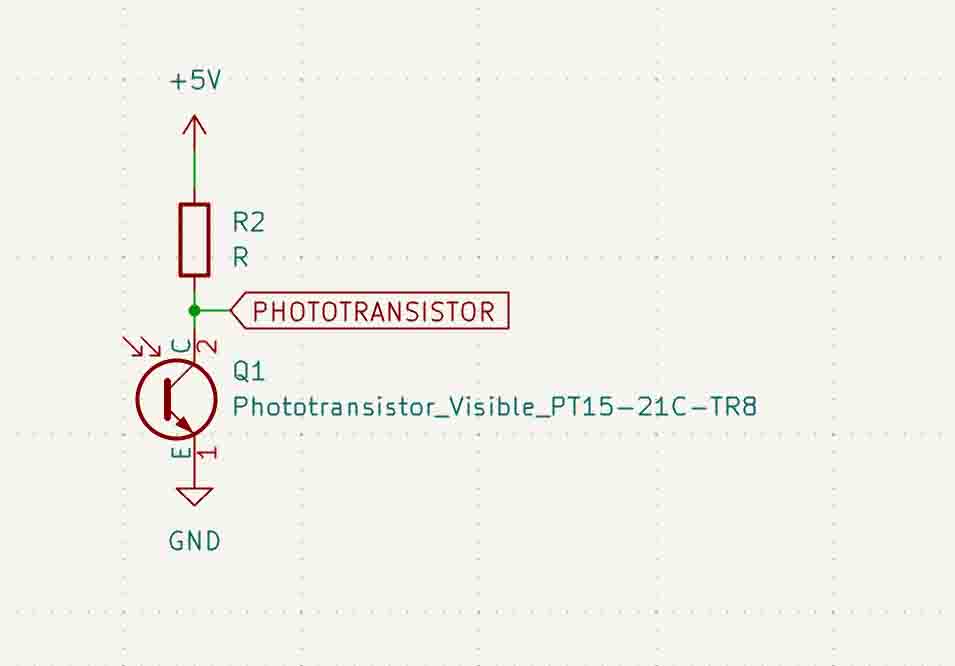
In order to find out what resistor is needed I used this formula: Resistance: R = VCC - VCE / IC, and looked in the datasheets for some info.
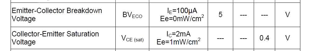

From these I can see that the phototransistors runs on 5V, the VCE is 0.4 and the absolute max IC current draw is 20 mA.

With a 2300 Ohm resistor I will be drawing the absolute max, and that is a bit risky. So I did the calculations of a 0.1 mA draw:

It resulted in a 4600 Ohm resistor. The closest we have to this is a 4.99kOhm resistor so I will be using that.
The closest we have is a 4.99 kOhm resistor and by doing this calculations I know that that will be fine as it will limit the current enough.
Humiditysensor BME280
Now to add a :humiditysensor
I found the sensor I am using among the components in KiCad.

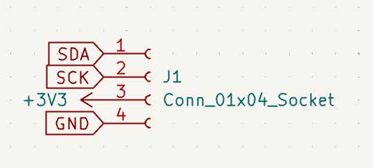
But I quickly realised that since I will be using a sensor that has pre-soldered pins on it I actually need pin sockets. I will only be using 4 pins, but there are 7 solderes on already. I therefore use a 6 pin socket.
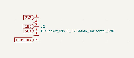
I had been marking the SDA-pin with a humidity label, but since I will be using the I2C communication with another component I changed it to SDA for clarity:
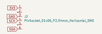
Henk reminded me that a resistor is needed with the button and to check if there is a pullup resistor in the pin I am connecting the button to.After checking thsi I moved it to a pin with a pullup resistor: pin D9, which is also pin 10 in the schematic. At this point I also realised I had connected the SDA label to the wrong pin. It needed to be on D4, but that is pin 5 and not 4.
OLED display
I want to add an oled dislay to display the humidity picked up by the sensor.
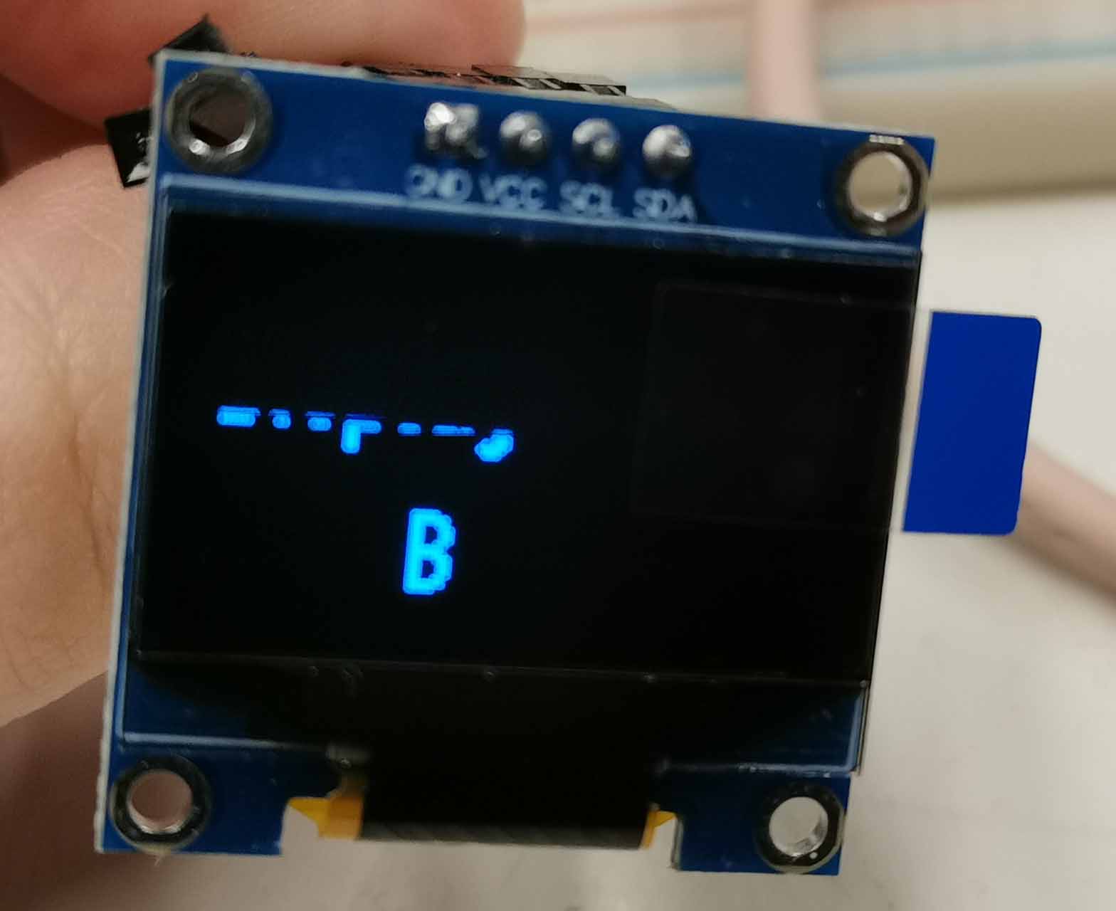
From looking in the datasheet I could see that for IC logic the board could run between 1.65V and 3.3V, but I got confused when it said minimum voltage 7V in another section of the sheet. I therefor quickly tested it to see that it could in fact be run by the esp32 board. VDD = 1.65V to 3.3V for IC logic
To test it out i used this site youtube video
And it wokred! I was worried I would need to supply 7V and then relgulate the Voltage down for the other components, but luckily that won't be necessary for this board.
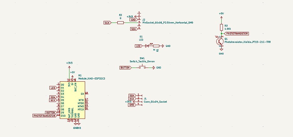
Here is the schematic for this component:
Here is the finished schematic:
footprints
On to adding footprints for all the components:
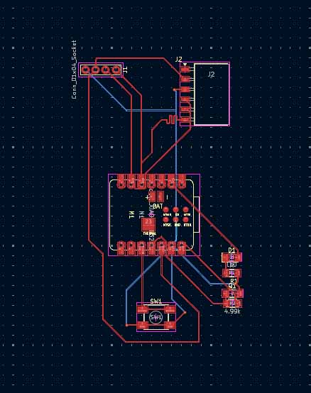
Routing
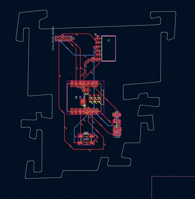
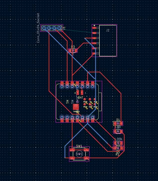
Time to pull the tracks of the board! This was svery tricky. Henk had warned me that it would take longer then I though and he was right. I wanted the board to look nice and a bit interesting so I first placed the components and then tried to make them fit together. It wasn't easy, but eventually I ended up with this:
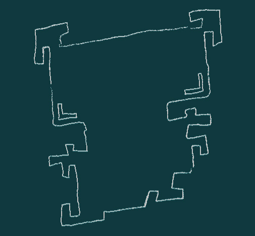
I played around with the edge cut a bit to see how funky I could make the board:

This was to test if parts could be cut away within the board aswell:
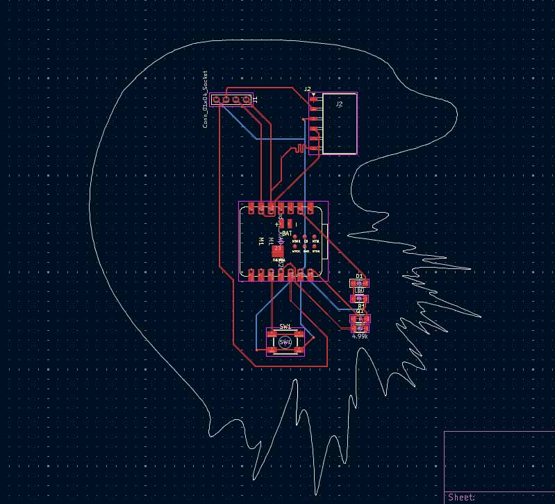
Since it seems I'm quite free to change the outline as I whish I sketched a new outline:
Made a vector of it in illustraitor:
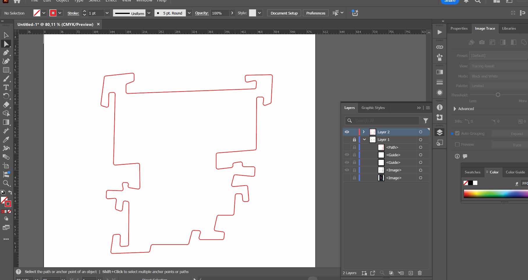
In order to import a costume graphic in KiCad I pressed import --> graphics --> make sure to have selected edge cutts as the correct layer --> enter.
I had forgotten to do my settings for the doscument, and filled these in:
Constraints:
Net classes:
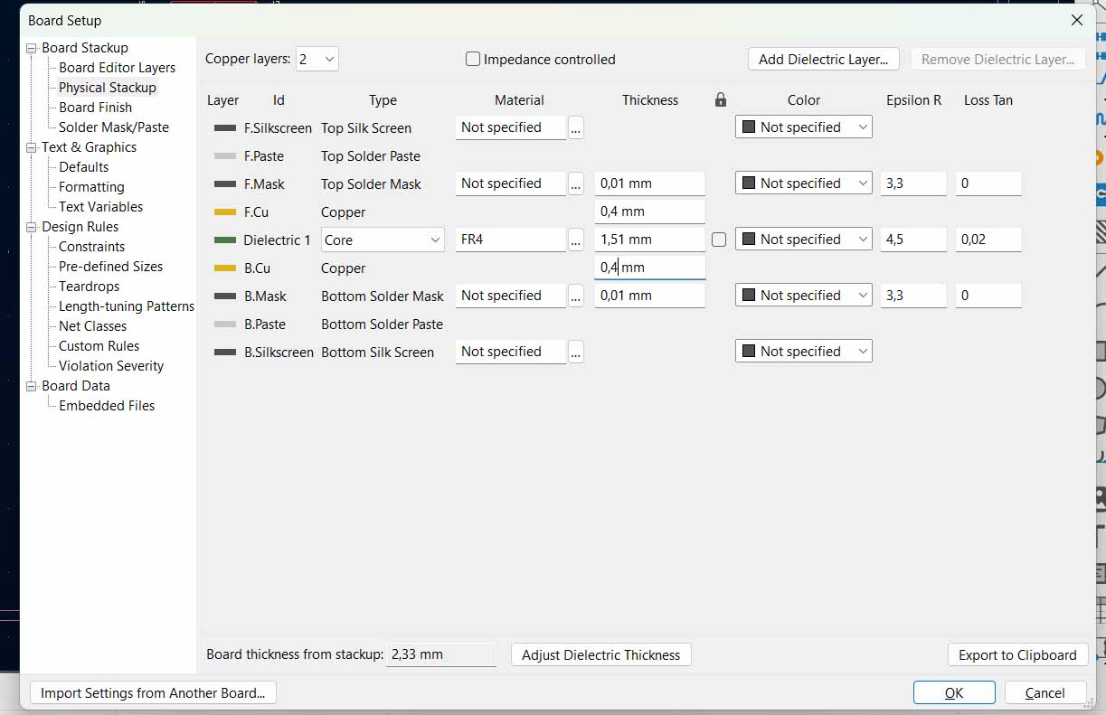
Physical stackup:
I was pretty happy with the board and it was time for a Design rules test:
It did not go well.
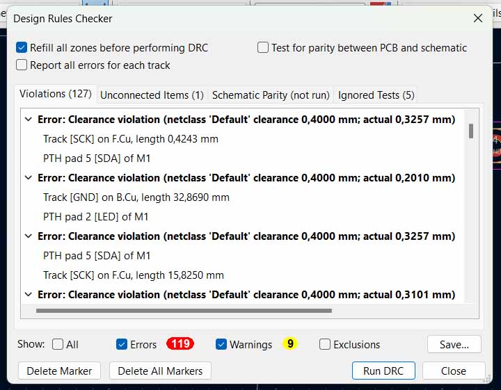
119 errors!!
I had routed everything without the right settings!
It was time to reroute everything... At this point I added a 0Ohm resistor for the humidity sensor so the SDA wire could reach its destination. And all the GND is getting routed to the back of the board.
The new Design rules test had a lot of mistakes aswell, but not 119. And they turned out to be snippets of the old wires still on the board, and some holed that were placed on top of each other. It was easy to fix and int the end there was now erreors. Only a few errors about the writing, but I think that is okay.
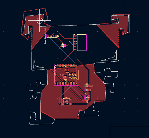
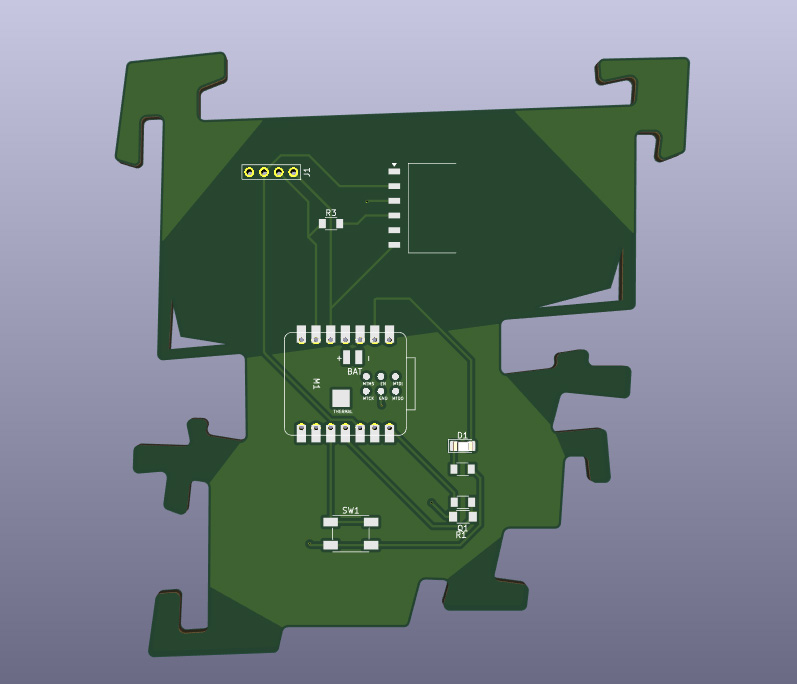
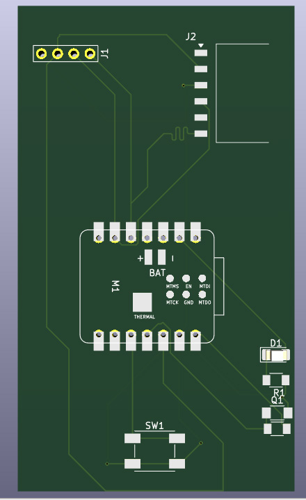
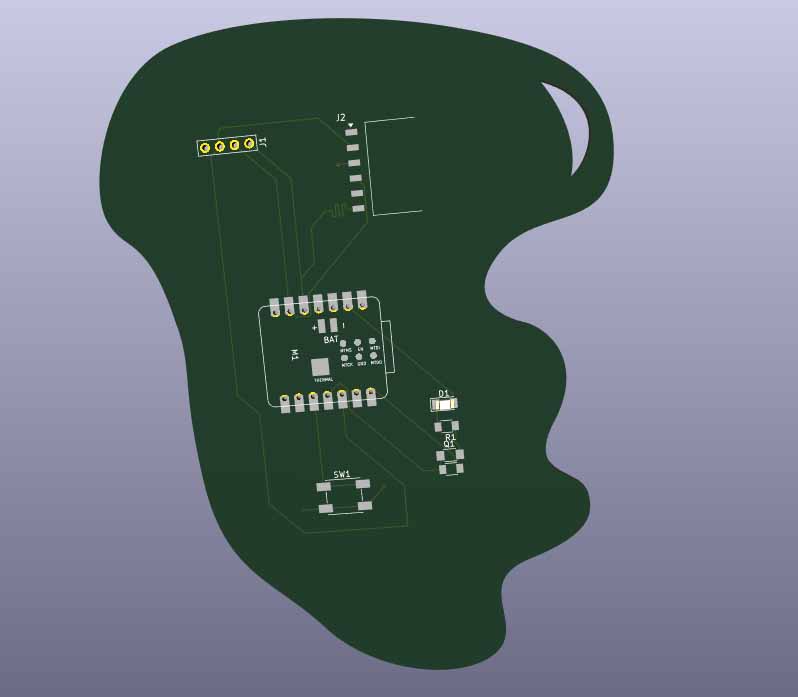
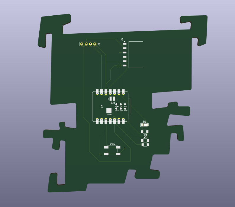
The final touch of this board is the copper fill: by using the Draw filled zones button on the right hand menu I sectioned off the parts I wanted filled in and presser B.
Here is the final result: