Embedded programming
Helpful links: RP's Programming languages Debugging Passing by value
Book:
The pragmatic programmer
Assignment
group assignment:
demonstrate and compare the toolchains and development workflows
for available embedded architectures
individual assignment:
browse through the data sheet for your microcontroller
write a program for a microcontroller,
and simulate its operation,
to interact (with local input &/or output devices)
and communicate (with remote wired or wireless connections)
extra credit: test it on a development board
extra credit: try different languages &/or development environments
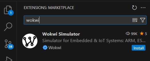
Wokwi in VSCode
Wokwi is an online Electronics simulator that can be used it to simulate Arduino, ESP32, STM32, and many other popular boards, parts and sensors. I will be using it for this weeks assignment and therefore want to set it up as an extention to VSCode
Is a simulatior. I can pic the ESP32 - C3
Download Pulseview
If you create your own function in VSCode - it must be called function(); - must be forward declared: void funtion(): at the top
Here is a guide on how to: set up Wokwi with VSCode
In the extentions I found the Wokwi simulator and installed it.
I then Clicked on the search bar, clicked F1, searched for Wokwi and clicked wokwi: start simulator. Then a small warning window popped up on the bottom right hand side of my screen and I clicked Get your Licence key. Clicked open on the window that popped up and got transfered to the Wokwi site.
On the site I saw that it is possible to get a 30 day free version of this extention. For now I don't know if it is possible to extend it, but I think so. The site says that the extention is free for non-commercial use so my guess is that it is possible to generate a new key after 30 days. After creating my account I recieved a key that got importet to Visual Studio Code when I got guided back to it.

Notes: Thursday meeting
On Thursday we got an introduction to embedded programming by Leo: FabLab Enschede
The goal of this week: Have something functional.
There are different coding languages:
C: c stands for code. It was developed by people who understood the chip. This way of coding is less safe because you need to build in your own safety structures.
C++: Arduino IDE, based on C, uses many layers of abstraction.
Rust: Supposedly the next C - more secure, will not allow you to write bad code // not very mature for microcontrollers, used mostly for applications
MicroPython: Cleaner and easier to read/understand The downside is that this does not work on all microcontrollers
RTOSor Real Time Operating System: runs on ESP32, raspberryPi ++, not on old AVRs. Dual core - you write on core-1, not core-0 (not possible)
Zephyr: Scalable, optimised, secure, multiple hardware architechtures(using a HAL)
Useful words and notes
Safety:
In terms of overriding, safety nets to avoind this and corruption
Compiler:
Translates HUC(human understandable code) to binary code
Programmer:
Transfer the binary code to the microcontroller
Bootloader:
- Runs at start of computer
- Do not use with new AVRs
- Eats away part of the Memory
- No bootloader: more space, but limits in other aspects depending on the boo=tloader in question
Space:
- All about memory
- Small microcontroller 8kb
Arduino: Bootloader connects microcontroller and IDE
Microcontrollers:
- Loops, can run 1 program at a time
How to select microcontroller:
- How many I/O ports do you need? HIGH/LOW (1/0) Digital pin
- What other pins are needed? (ADC converts voltage, DAC(Digital to analog converter) converts binary to voltage, SPI, I2C, I2S, UART: serial communication, timers++)
- Power consumtion / speed
- Operating voltage needed, also for parts
- Environmental impact
- Cost
- Registers: MC only understands binary
- Abstracted away, you can find it in the datasheet. Register names are in Arduino IDE translated into their own more readable code. Ex: PIN_MODE
Test:
- Troubleshooting
- Code + logging
- use serialPrint (write good description)
- LEDs
- Code + logging
Powering:
- Historcally: 5V
- Now: More 3.3V
- If too high: smoke and frustration
Input devices:
- 95% are related to voltage.
- Analog sinal = voltage
Pins:
- IO pins: HIGH/LOW (1/0) Digital pin
- ADC (Analog to Digital converter) converts voltage
- DAC (Digital to analog converter) converts binary to voltage
- UART: serial communication
LEDs:
- Always blinking
- No LEDs in chickeCoops
Multiplexer: possible to use a small MCU - split one pin into many more.
Arduino:
- DevBoard - UNO: 20 years old
- toolchains
- Software Library
- IDE
- Bootloader
- Header Harware resourses claimed:
Common commands: - pinMode() - analogRead() - analogWrite() - digitalRead() - digitalWrite() - Serial.begin() - Serial.print()
Xiao-boards
- Seeed Studio
- bootloader already on the board
- Can use adruino libraries
Other IDES
- Eclipse
- Atmel Studio
- Visual studio code
Tips:
- Always put an LED on the board
- Use variables that fit the processor
Programming software
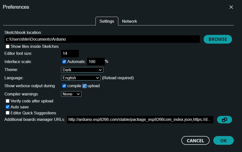
Arduino IDE has some preinstalled boards, but sometimes its necessary to install thhe right board. This is done by pressing file --> preferences --> there you can add boards by clicking on the small icon next to `Additional moard manager URLs. We were provided with these URLs to add to the program:
  https://descartes.net/package_drazzy.com_index.json,
  https://github.com/earlephilhower/arduino-pico/releases/download/global/package_rp2040_index.json,
  https://raw.githubusercontent.com/espressif/arduino-esp32/gh-pages/package_esp32_index.json,
  https://raw.githubusercontent.com/qbolsee/ArduinoCore-fab-sam/master/json/package_Fab_SAM_index.json
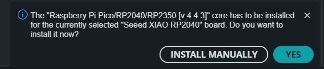
XIAO-RP2040 and LEDs
Is a baord we used in the introduction. There is more specified info about further down in the comparason section.
To test that a board is working and it is possible to upload to it we used the example code Blink. This can be found under file --> examples --> 01.Basics
After loading the sketch plug in the board (if that's not already done), select the correct board at the top of the page, and upload.
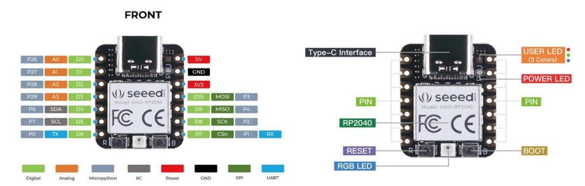
Heres some info about the XIAO-RP2040s built in LEDs:
The board has 5 LEDs on the board. There are 3 on the top right side. These are in the colors Red, Blue, and Green, and can be controlled individually. Underneath them there is a stronger red LED and finally at the centre base of the board there is a Neopixel.
When programming these lights it is important to note that for the LEDs HIGH means OFF, and LOW means ON.
LEDs work with Puls Width Modulation or PWM. THis means that they are always turning off and on. When the LED is dimmer it just means that is has a longer interval of being off in comparason to on.
Here is how to set up the use of the built in RGB-LEDs on the board:
  void setup() {
        // initialize digital pins for LEDs as outputs.
        pinMode(PIN_LED_R, OUTPUT);
        pinMode(PIN_LED_G, OUTPUT);
        pinMode(PIN_LED_B, OUTPUT);
        // Turn off LEDs
        digitalWrite(PIN_LED_R, HIGH);
        digitalWrite(PIN_LED_G, HIGH);
        digitalWrite(PIN_LED_B, HIGH);

  }
This setup function only runc once: when the program starts up after that it moves on to the loop function which it keeps looping through. That is were an animation of the lights can be made. Dylan was talking about a breathing exesise he likes to do where you breathe in for 4 sec, hold for 7 sec and breathe out for 8 sec. I tried to make a simple guide for this.
  void loop() {
        // Breathe in
        digitalWrite(PIN_LED_G, LOW);  // turn the blue LED on
        delay(4000);                   // wait for a second
        digitalWrite(PIN_LED_G, HIGH); // turn the blue LED off
        delay(10);                   // wait for a second

        // Hold breath
        digitalWrite(PIN_LED_R, LOW);  // turn the red LED on
        delay(7000);                   // wait for a second
        digitalWrite(PIN_LED_R, HIGH); // turn the red LED off
        delay(10);                   // wait for a second

        //Breathe out
        digitalWrite(PIN_LED_B, LOW); // turn the LED off
        delay(8000);                   // wait for a second
        digitalWrite(PIN_LED_B, HIGH); // turn the LED off
        delay(10);                   // wait for a second

        }
The Neopixel LED is a bit different. TO use it we installed the library FastLED, and then using the examplecode from that library, also called Blink, we programmed it. Nothing happened. That is because in order to use that pin we need to enable it. In the datasheet ww could see that the NEOPIXEL is pin 12, but the enable ping for it is pin 11. We therefore started the code by setting pin 11 to HIGH.
  #include <FastLED.h>

  // How many leds in your strip?
  #define NUM_LEDS 1

  // build in neopixel pin XIAORP-2040
  #define DATA_PIN 12

  // Define the array of leds
  CRGB leds[NUM_LEDS];

  void setup() {
        // Set Enable pin to output
        pinMode(11, OUTPUT);

        // Set Enable to on - this will enable the led on the board.
        digitalWrite(11, HIGH);

        // GRB ordering is assumed
        FastLED.addLeds<NEOPIXEL, DATA_PIN>(leds, NUM_LEDS);

        }

  void loop() {

        // Turn the LED on, then pause
        leds[0] = CRGB::Navy; // prepares data
        FastLED.show(); // Sends data
        delay(500);

        // Now turn the LED off, then pause
        leds[0] = CRGB::Black; // prepares data
        FastLED.show(); // sends data
        delay(500);
  }
Troubleshooting
It could be that the wrong bootloader is installed on the board. To boot it hold the B button, and whilst holding that in click the E button, and release the B button again. The board will then show up as a usb device on the computer and the new bootloader can be dropped in there. Some programs will tell you if the bootloader is wrong and ask if they should cahnge it for you. This happened when I plugged my board into the Arduino IDE.
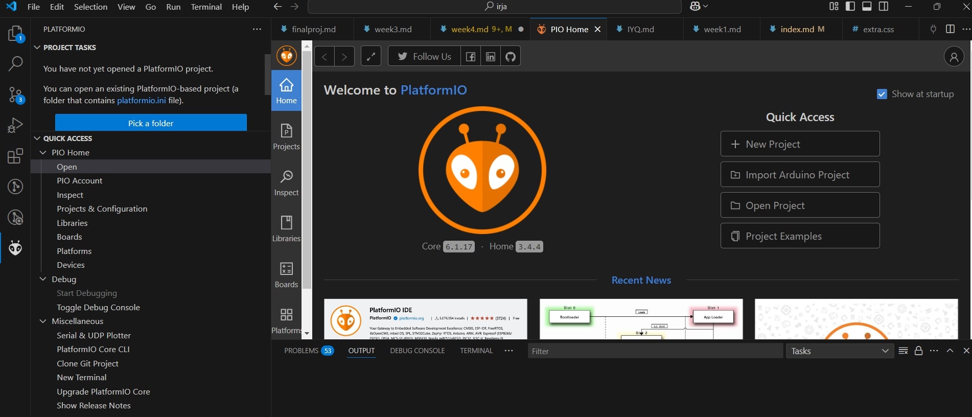
PlatformIO and Visual studio Code
Slides for Platfor IO and VSC by Leo Kuiper
What is platfor IO: A plugin to VSC, IDE Frameowrk: C/C++
Cross-platform IDE which supports many different C/C++ software development kits (SDKs, called Frameworks in platformIO) and includes a lot of sophisticated developer tools.
Why use it? - It works good - Can do more then Arduino IDE - Can work with extentions. - c/c++ --> intellisesce --> autocomplete! - Git directly for the editor - Github copolot --> Use copolot AI to help you to program code - Copilot is now free! - PlatformIO adds embedded programming to VSC
SDK Software Developement kit - framework - why?
- Not start from scratch
- Toolbox with libraries that work, and expample codes, debugging ect.
- ESP32: SDK: IDF
- RP: PicoSKD
Steps: - Install extention: PlatformIO IDE
- Install extention: C/C++
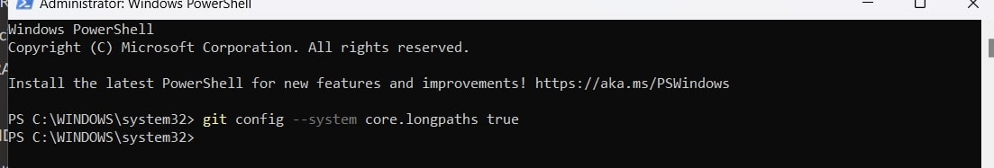
When using a windows computer there are some issues that arises. This is beacuse there is a limit to how long the path can be io platform IO. I therefore had to open my terminal as administraitor and typ in this:
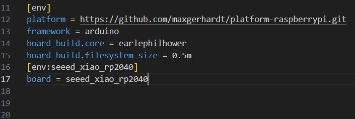
Then go into the platformio.ini file and delete what is there and replace it with:
MicroPython
Reset the board in the same way as mentioned in the Arduino IDE section: hold B and click E. The microcontroller mimics a usb drive: Look for the RPI-RP2-file, It is now in Bootloader mode: any bootloader can me loaded on.
Go to micropython website, install bootloader Download PICO and drag in onto the thumbdrive. It will now dissapear and the bootloader is installed.
Micropyton has an operating system.
Oficcial Raspberry pi PicoExtention VSC: code in C/C++, but the Pico SDK framework. Note that Arduino libraries do not work with this micropython
You can upload a file to micropython, but it needs a specific name in order to be booted when powered up again. THe file bust be named boot.py
There are 2 ways to upoad a to your microcontroller: * Upload project: uploads all the files from your project - Upload file: only the file (creates trouble if you are using extra libraries)
Data sheets!!
After this intro it's time to look at the datasheets of the board I'll be using. Eventually I think I will need my boards to communicate with each other. Even if I do not need that application now, it would be a good option to have. At Waag we were given 2 microcontrolles: XIAO-RP2040 and XIAO-ESP32-C3
To get more familiar with tham I went through this collected datasheet for the XIAO-series Systems-on-Modules User manual.
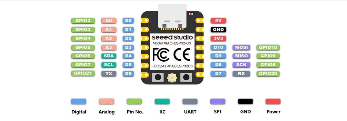
Xiao means Tiny in Chinese which is fitting to these modules as the boards are small. This makes them great for wearable projects. All the modules in the Xiao series has the same pinouts.
In the assignment it said to look into the datasheet of one board, but since I'm not sure what the difference is between the two we were given I was happy to find a guid with info of both of them. To my delight the first section of the sheet had a selection guide comparing all of the XIAO SoM boards: (and its green!)
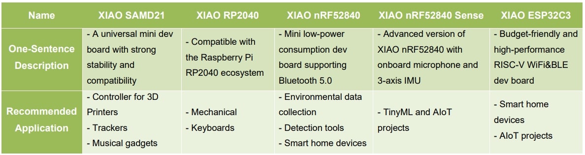
When comparing the RP2040 and ESP32-C3 for my final project which will hopefully result in a few mechanical arms it looks as though I will be using the RP2040, but lets keep reading before makign a desition.
XIAO-RP2040
Power Consumption: 28.9 mA
Operating Voltage and Supply Voltage: Operating Voltage is 5V (Type C)
Bootloader: Standard Bootloader for common PC port identification, UF2 Bootloader for CircuitPython usage of PC port identification
Programming Languages: Arduino, MicroPython, and CircuitPython
Clock: There is a build in crystal oscillator which provides a precise, stable clock reference.
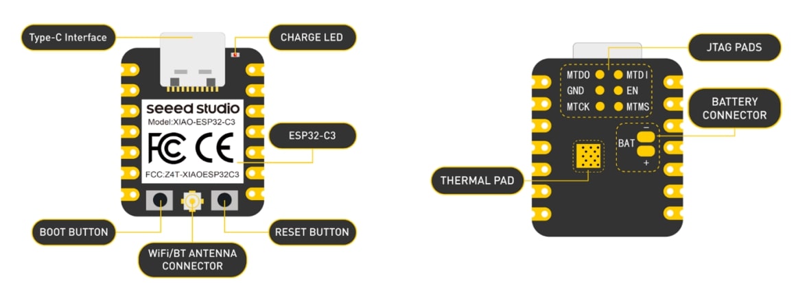
XIAOESP32-C3
Power Consumption: 25.7mA (Low power model: <44uA)
Operating Voltage and Supply Voltage: Type C: 5V, Battery: 3.7V Li-On
Charging current: 380mA±30mA
Bootloader: Standard Bootloader for common PC port identification
Programming Languages: Arduino
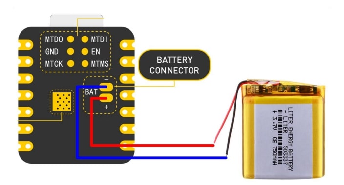
How to power the XIAOESP32-C3 by battery:
- Make sure to use a proper battery that meets the specifications
- There is a safety built in that will allow the board to be connected to computer via data cable whilst powered by battery.
- There will be no LED indication when the board is powered by battery, unless it is written into the code.
Comparason
To make an easier overview here is a comparason of the two:
| XIAO-RP2040 | XIAOESP32-C3 | |
|---|---|---|
| Processor | RP2040 | ESP32C3 |
| RAM | 264 KB SRAM | 400 KB SRAM |
| Flash(chip) | No | 4MB |
| Flash(onboard) | 2MB | 4MB |
| Build-in-sensors | No | No |
| PWM/analog pins | 11/4 | 11/4 |
| I2C/UART/SPI | Yes | Yes |
| Bluetooth | No | Yes |
| WiFi | No | Yes |
| Reset button | Yes | Yes |
| Boot Button | Yes | Yes |
| User LED | Yes | No |
| Battery Charge LED | No | Yes |
| Battery Charge IC | No | Yes |
| Low power mode | No | <44μA |
| Arduino | Yes | Yes |
| CircuitPyton | Yes | No |
| MicroPython | Yes | No |
| Product life | 3+ years | 3+ years |
| Power consumption | 28.9 mA | 25.7mA |
| Operating Voltage | 5V | 5v / 3.7V |
Project: Humidify my house
Now that I've looked at the boards I think I will use the XIAOESP32-C3 for this weeks assignment. It can only be programmed using arduino or C++, but that's alright for me. I also like to have the opportunity to connect it wirelesly with other boards if needed. I have therefore decided to make the base for a humidifier in my house. My plan is to make a humidifier that ac ctivates whenever the humidity drops below 40%, and realses different sents based on what time of day it is.

For this I plan to use a DHT22 humitity and temperature sensor, a 16x2 LCD display with IC2 adapter, relays, ultrasonic mistmakers and a XIAOESP32-C3.
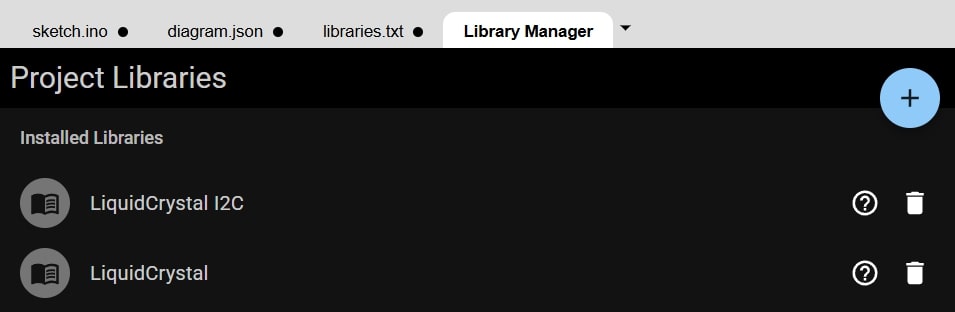
I'm testing this out in wokwi. First I needed to add the Liquid Crystal library. THat can be done by navigating to the library manager on the top left part of the screen and seraching fo rthe needed library. In this case it automatically added both the Licuid crystal library and the one for Liquid crystal I2C, which is what I am using.
From the data sheets I can see that the LCD screen connected through the I2C has 4 pins. GND, VCC, SDA and SCL. By looking at the datasheet from XIAOESP32-C3 I see that the SDA pin goes to pin 4 and SCL to pin 5.
16x2 LCD display with IC2 adapter
| Model | I2C Serial Interface 1602 LCD Module |
|---|---|
| Power supply | 5V |
| Display Type | Negative white on Blue backlight. |
| I2C Address | 0x38-0x3F (0x3F default) |
| Interface | I2C to 4bits LCD data and control lines |
| Contrast Adjustment | built-in Potentiometer |
First code:
  // Include the library
  #include <LiquidCrystal_I2C.h>

  // Add the lcd
  LiquidCrystal_I2C lcd(0x27, 16, 2);

  void setup() {
  // Initalise the LCD
  lcd.init();
  // Turn on the LCD backlight
  lcd.backlight();
  // Put text on the LCD
  lcd.print("Hello World!");
  }

  void loop() {

  }
In the wokwi simulator the first attemt looks like this:
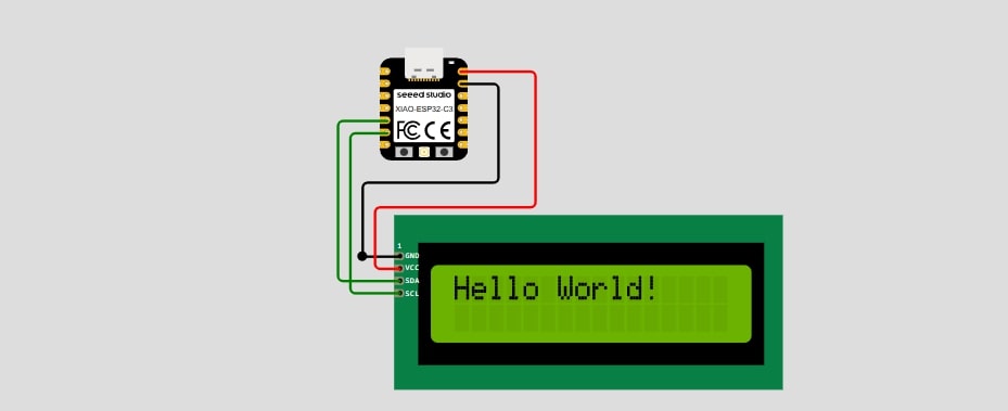
Now that the LCD screen is hooked up correctly it's time to add a humifidier.
First some info about the DHT22 sensor.
| Model | DHT22 |
|---|---|
| Power supply | 3.3-6V DC |
| Output signal | digital signal via single-bus |
| Operating range | humidity 0-100%RH; temperature -40~80Celsius |
| Accuracy | humidity +-2%RH(Max +-5%RH); temperature <+-0.5Celsius |
| Long-term Stability | +-0.5%RH/year |
| Sensing period | Average: 2s |
| Interchangeability | fully interchangeable |
I started by adding the library DHT22. The sensor has 4 legs. the 1st is VCC, 2nd in DATA (here the signal will come through), 3rd is NULL, and the 4th is GND.
In the datasheet I read that when the sensor is powered I need to wait 1 second before sending any data to it. I therefore add a delay (1000) in void setup. And that One capacitor valued 100nF can be added between VDD and GND for wave filtering. I cannot find this component in wokwi, but will make a note of it for the schimatic and the practical setup. For the practical set up it's also worth to not that this sensor will need to be kept out ofstron light and UV light since this will affect the preformance.
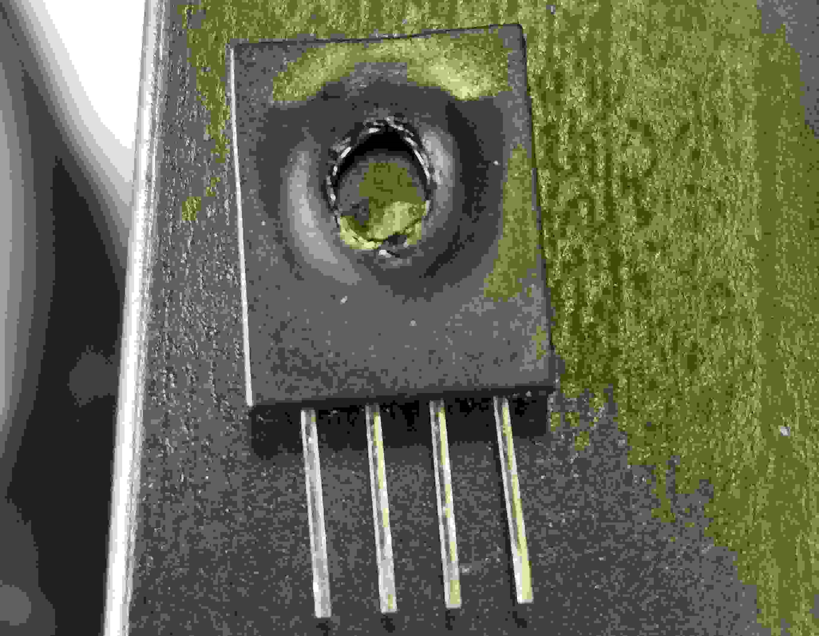
Wokwi was being very slow and could not upload the code so I therefore dicided to test it out on a breadboard. I wiered everything up and plugged the board in and suddenly there was a burt smell. I had put the sensor the wrong way around and inverted the polarities. Sam told me he had had the same issue when using this sensor it the university. Sloppy wiring by me.
I want to code my project in PlatforIO in Visual Studio Code. I open a new project and add the DHT sensor library form Adafruit.
Here is my first test code for the humidity sensor:
  // include arduino
  #include <Arduino.h>

  // include library for DHT22
  #include <DHT.h>

  // Define humidifier pin
  #define DHTpin 2 // GPI02 XIAO ESP32-C3
  #define DHTTYPE DHT11 // DHT 22 (AM2302)
  DHT dht(DHTpin,DHTTYPE); // Initialise HDT senor

  // Variables

  float humidity;     // stores humidity value
  float temperature;  // stores temperature value

  void setup() {
  Serial.begin(9600); // serial communication
  dht.begin(); // Communication with sensor

  delay(1000); // delay 1 sec to allow sensor to start up
  }

  void loop() {


  // Read data and store it to the variables humidity and temperature
  hum = dht.readHumidity();
  temp = dht.readTemperature();

  // Print temp and humidity values to serial monitor
  Serial.print("Humidity: ");
  Serial.print(hum);
  Serial.print(" %, Temperature: ");
  Serial.print(temp);
  Serial.print(" Celcius");

  // Delay -- 2 sec -- the sensor samples are every 2 sec
  delay(2000);

  }
I had to exchange the DHT22 for a DHT11, an older version since i burnt through the other one. Sam had a good tip for me: Keep a finger on the sensor when you plug it in. If it gets warm quikly unplug it. THen it can still be saved. And also always check the wiring.
I got some faults: * hum and temp not identified. I had changed them from temperature and humidity in the void loop, but not when they were declared. * Could not read sertial monitor: I had not chosen the correct USBPORT and needed to change the baud rate to 9600. This also did not help, but by looking ina forum I saw that I needed to declare
monitor_speed = 9600
in the platformio.ini file.
I then tried againg and there is still a problem with finding the port for the serial monitor. I tried holding Boot and clicking Enable whilst holding boot. Still did not work. So I decided to try to upload the code from arduino IDE.
It uploaded fine after installing the DHT library, however the serial monitor only displayed the values nan:
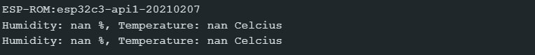
Time to look at the datasheet for the DHT11
I tried switching the sensor out for another DHT22, but it still sais NAN as values. Sam came over to help me and we switched the sensor with one of his and then it worked. Turns out the sensors I used were broken. THe new code had some serial prints to help keep track of if the sensor has started and are looping:
  // include arduino
  #include <Arduino.h>

  // include library for DHTmodule
  #include <DHT.h>

  // Define humidifier pin
  #define DHTpin D3           // GPI02 XIAO ESP32-C3
  #define DHTTYPE DHT11      // DHT 11
  DHT dht(DHTpin, DHTTYPE);  // Initialise HDT senor

  // Variables

  float hum;   // stores humidity value
  float temp;  // stores temperature value

  void setup() {
  Serial.begin(9600);  // serial communication
  dht.begin();         // Communication with sensor
  Serial.println("started"); // to see if its started
  delay(1000);  // delay 1 sec to allow sensor to start up
  }

  void loop() {
  // Delay -- 2 sec -- the sensor samples are every 2 sec
  delay(2000);
  // to see if its looping
  Serial.println("loop");

  // Read data and store it to the variables humidity and temperature
  hum = dht.readHumidity();
  temp = dht.readTemperature();

  // Print temp and humidity values to serial monitor
  Serial.print("Humidity: ");
  Serial.print(hum);
  Serial.print(" %, Temperature: ");
  Serial.print(temp);
  Serial.println(" Celcius");


  }
Now to combine the 2 codes so far:
  // include library for DHT22 and LCD
  #include <DHT.h>
  #include <LiquidCrystal_I2C.h>

  // Define humidifier pin
  #define DHTpin D3           // GPI02 XIAO ESP32-C3
  #define DHTTYPE DHT11      // DHT 22 (AM2302)
  DHT dht(DHTpin, DHTTYPE);  // Initialise HDT senor

  // Variables

  float hum;   // stores humidity value
  float temp;  // stores temperature value

  // Add the lcd
  LiquidCrystal_I2C lcd(0x27, 16, 2);

  void setup() {
  Serial.begin(9600);  // serial communication
  dht.begin();         // Communication with sensor
  Serial.println("started");
  delay(1000);  //delay 1 sec tod allow sensor to start up

  // Initalise the LCD
  lcd.init();
  // Turn on the LCD backlight
  lcd.backlight();
  // Put text on the LCD
  lcd.print("Hello World!");
  }

  void loop() {
  delay(2000);
  Serial.println("loop");

  // Read data and store it to the variables humidity and temperature
  hum = dht.readHumidity();
  temp = dht.readTemperature();

  // Print temp and humidity values to serial monitor
  Serial.print("Humidity: ");
  Serial.print(hum);
  Serial.print(" %, Temperature: ");
  Serial.print(temp);
  Serial.println(" Celcius");

  // Delay -- 2 sec -- the sensor samples are every 2 sec
  }
I now have a working display and a sensor that reads the temperature and humidity. Lets display that on the LCD:
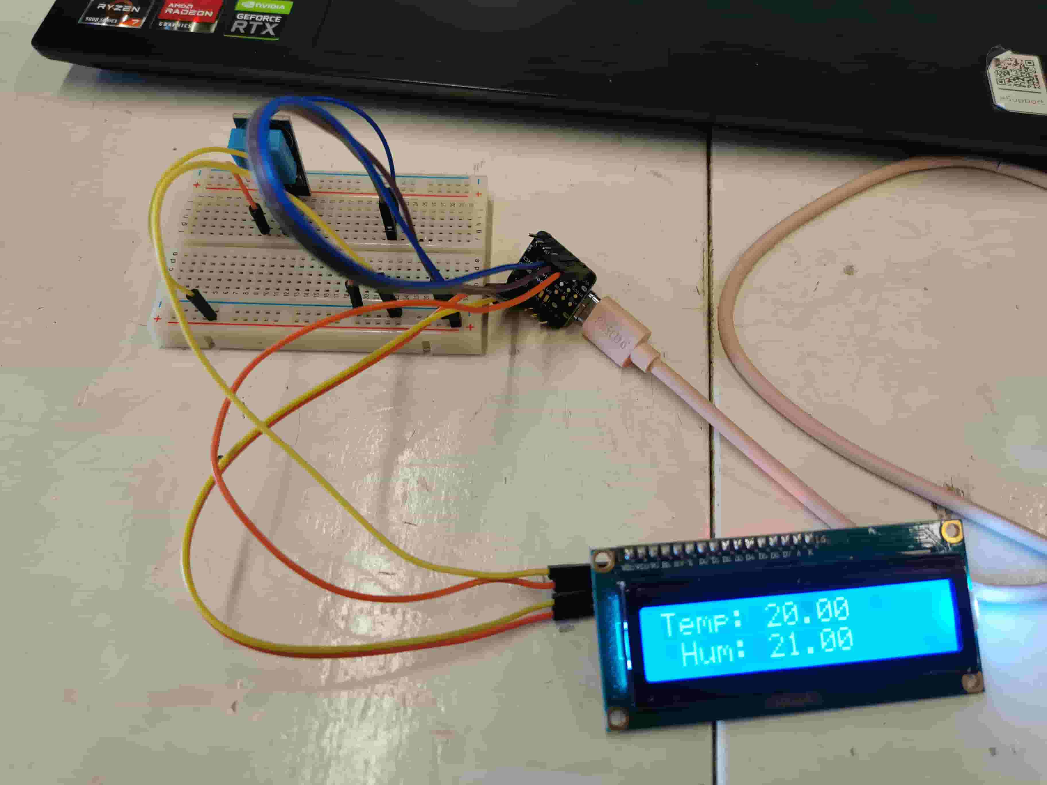
Here is the next part of the code. Here there are 3 relays added, with this code it is possible to check that the relays, humidity sensor and the lcd screen works:
  // include library for DHT22 and LCD
  #include <DHT.h>
  #include <LiquidCrystal_I2C.h>

  // Define humidifier pin
  #define DHTpin D3           // GPI02 XIAO ESP32-C3
  #define DHTTYPE DHT11      // DHT 22 (AM2302)
  DHT dht(DHTpin, DHTTYPE);  // Initialise HDT senor

  // Variables

  float hum;   // stores humidity value
  float temp;  // stores temperature value

  // Add the lcd
  LiquidCrystal_I2C lcd(0x27, 16, 2);

  // intergers for relays
  int R_1 = D10;
  int R_2 = D9;
  int R_3 = D8;

  void setup() {
  Serial.begin(9600);  // serial communication
  dht.begin();         // Communication with sensor
  Serial.println("started");


  // Initalise the LCD
  lcd.init();
  // Turn on the LCD backlight
  lcd.backlight();
  // Put text on the LCD
  lcd.print("Hello World!");

  pinMode(R_1, OUTPUT);
  pinMode(R_2, OUTPUT);
  pinMode(R_3, OUTPUT);

  delay(1000);  //delay 1 sec tod allow sensor to start up
  }

  void loop() {
  delay(2000);
  Serial.println("loop");

  // Read data and store it to the variables humidity and temperature
  hum = dht.readHumidity();
  temp = dht.readTemperature();

  // Print temp and humidity values to serial monitor
  Serial.print("Humidity: ");
  Serial.print(hum);
  Serial.print(" %, Temperature: ");
  Serial.print(temp);
  Serial.println(" Celcius");

  lcd.clear(); // clear the LCD screen
  lcd.setCursor(0,0);
  lcd.print("Temp: ");
  lcd.print(temp);

  lcd.setCursor(0,1);
  lcd.print(" Hum: ");
  lcd.print(hum);

  digitalWrite(R_1, HIGH);
  delay(1000);
  digitalWrite(R_2, HIGH);
  delay(1000);
  digitalWrite(R_3, HIGH);
  delay(1000);
  digitalWrite(R_1, LOW);
  delay(1000);
  digitalWrite(R_2, LOW);
  delay(1000);
  digitalWrite(R_3, LOW);
  delay(1000);


  }
Onto the main part: Its time to make the code do what I want it to do. The ideal humidity in a house is between 40% and 60%. As long as the humidity in the house is under 60% there should not be a risk of mold forming. I will therefore set the module to start humidifying at 45% and stop at 55%. If humidity is over 60% then the display should write: Open a window!!
  if (hum > 60){
  lcd.clear(); // clear the LCD screen
  lcd.setCursor(0,0);
  lcd.print("Open a window!!");
  }
Ideally this humidifier will have 4 separate chambers which each are active at differents times of day. I therefore need to use some kind of clock. I remember reading that the ESP32 has a built in clock.
I first install the library "esp32time". I am using this as my guide.
I added to the code :
      #include <ESP32Time.h>

      ESP32Time rtc(3600);

      void setup(){
            rtc.setTime(30, 54, 14, 18, 2, 2025);  // 18th Feb 2025 14:54:30
      }

      void loop(){
            Serial.println(rtc.getHour(true));      //  (int)     15    (0-23)
      }
I can now see the number 15 printed in the serial monitor indicating that we are in hour 15 of the day. This number can be used to change which of the relays are activated when the humidity changes. I had to invert the values for the Relays so that HIGH means off and LOW means on. Here is the final code:
  // include library for DHT22 and LCD
  #include <DHT.h>
  #include <LiquidCrystal_I2C.h>
  #include <ESP32Time.h>

  // Define humidifier pin
  #define DHTpin D3           // GPI02 XIAO ESP32-C3
  #define DHTTYPE DHT11      // DHT 22 (AM2302)
  DHT dht(DHTpin, DHTTYPE);  // Initialise HDT senor

  // Variables

  float hum;   // stores humidity value
  float temp;  // stores temperature value

  // Add the lcd
  LiquidCrystal_I2C lcd(0x27, 16, 2);

  // intergers for relays
  int R_1 = D10;
  int R_2 = D9;
  int R_3 = D8;
  int R_4 = D7;

  ESP32Time rtc(3600);

  void setup() {
        Serial.begin(9600);  // serial communication
        dht.begin();         // Communication with sensor
        Serial.println("started");

        // Initalise the LCD
        lcd.init();
        // Turn on the LCD backlight
        lcd.backlight();
        // Put text on the LCD
        lcd.print("Hello World!");

        pinMode(R_1, OUTPUT);
        pinMode(R_2, OUTPUT);
        pinMode(R_3, OUTPUT);
        pinMode(R_4, OUTPUT);

        // set time
        rtc.setTime(30, 54, 14, 18, 2, 2025);  // 18th Feb 2025 14:54:30

        delay(1000);  //delay 1 sec tod allow sensor to start up
  }

  void loop() {
        delay(2000);
        Serial.println("loop");
        Serial.println(rtc.getHour(true));      //  (int)     15    (0-23)

        // Read data and store it to the variables humidity and temperature
        hum = dht.readHumidity();
        temp = dht.readTemperature();

        // Print temp and humidity values to serial monitor
        Serial.print("Humidity: ");
        Serial.print(hum);
        Serial.print(" %, Temperature: ");
        Serial.print(temp);
        Serial.println(" Celcius");

        lcd.clear(); // clear the LCD screen
        lcd.setCursor(0,0);
        lcd.print("Temp: ");
        lcd.print(temp);

        lcd.setCursor(0,1);
        lcd.print(" Hum: ");
        lcd.print(hum);

        if (hum > 60){
              lcd.clear(); // clear the LCD screen
              lcd.setCursor(0,0);
              lcd.print("Open a window!!");
              digitalWrite(R_1, HIGH);
              digitalWrite(R_2, HIGH);
              digitalWrite(R_3, HIGH);
              digitalWrite(R_4, HIGH);
        }

        if (hum <= 55 && rtc.getHour(true) >= 0 && rtc.getHour(true) <= 5) {
              digitalWrite(R_1, LOW);
              digitalWrite(R_2, HIGH);
              digitalWrite(R_3, HIGH);
              digitalWrite(R_4, HIGH);
        }

        if (hum <= 55 && rtc.getHour(true) >= 6 && rtc.getHour(true) <= 11 ) {
              digitalWrite(R_1, HIGH);
              digitalWrite(R_2, LOW);
              digitalWrite(R_3, HIGH);
              digitalWrite(R_4, HIGH);
        }

        if (hum <= 55 && rtc.getHour(true) >= 12 && rtc.getHour(true) <= 17) {
              digitalWrite(R_1, HIGH);
              digitalWrite(R_2, HIGH);
              digitalWrite(R_3, LOW);
              digitalWrite(R_4, HIGH);
        }

        if (hum <= 55 && rtc.getHour(true) >= 18 && rtc.getHour(true) <= 23) {
              digitalWrite(R_1, HIGH);
              digitalWrite(R_2, HIGH);
              digitalWrite(R_3, HIGH);
              digitalWrite(R_4, LOW);
        }

        if (hum >= 56) {
              digitalWrite(R_1, HIGH);
              digitalWrite(R_2, HIGH);
              digitalWrite(R_3, HIGH);
              digitalWrite(R_4, HIGH);
        }

  }
Now I can test it out properly. I know from last time I worked with the humidity modules that they need to be powered separatley from the microcontroller. I have also rearnt that I need to surpass the button on the module. I have been talking with Sam on how to do it and i have an idea. I first tried soldering the button so it's always pressed, but that ended up making a beeping sound the whole time. I also realise that I don't really have time to finish the physical computing part of this this week, but that's okay since the focus in embedded programming.
I do however have time to change the code a bit. Since having the button pressed for a longer time causes a beeping sound it is better to have it pressed once to initialise humidification and then pressed again to stop. This means that the code needs to change. Sam was a great help in making sense of this.
This change means the microcontroller needs to keep track of wether a button has been pressed or not in order to know if it will turn the humidifier on or off. I added booleans for the 4 relays to know if the button is true (clicked and on) or false (clicked and off)
bool R_button_1 false
bool R_button_2 false
bool R_button_3 false
bool R_button_4 false
I then created a rest function to be called in the beginning of each of the if statements. This is to make sure all the humidifiers are off to begin with to avoind muldiple being on at the same time.
Going back to the if statements related to humidity and time of day. Now that reset function is called in the beginning of each loop I could remove some of the digitalWrites. Now the relay presses the button ofr half a second and changes the boolean for that part to true.
  if (hum <= 40 && rtc.getHour(true) >= 0 && rtc.getHour(true) <= 5) {
        reset();
        digitalWrite(R_1, LOW);
        delay(500);
        digitalWrite(R_1, HIGH);
        R_button_1 = true;
  }
So here is the final code!
  // include library for DHT22 and LCD
  #include <DHT.h>
  #include <LiquidCrystal_I2C.h>
  #include <ESP32Time.h>

  // Define humidifier pin
  #define DHTpin D3           // GPI02 XIAO ESP32-C3
  #define DHTTYPE DHT11      // DHT 22 (AM2302)
  DHT dht(DHTpin, DHTTYPE);  // Initialise HDT senor

  // Variables

  float hum;   // stores humidity value
  float temp;  // stores temperature value

  // Add the lcd
  LiquidCrystal_I2C lcd(0x27, 16, 2);

  // intergers for relays
  int R_1 = D10;
  int R_2 = D9;
  int R_3 = D8;
  int R_4 = D7;


  bool R_button_1 false
  bool R_button_2 false
  bool R_button_3 false
  bool R_button_4 false

  ESP32Time rtc(3600);

  void setup() {
  Serial.begin(9600);  // serial communication
  dht.begin();         // Communication with sensor
  Serial.println("started");

  // Initalise the LCD
  lcd.init();
  // Turn on the LCD backlight
  lcd.backlight();
  // Put text on the LCD
  lcd.print("Hello World!");

  pinMode(R_1, OUTPUT);
  pinMode(R_2, OUTPUT);
  pinMode(R_3, OUTPUT);
  pinMode(R_4, OUTPUT);

  // set time
  rtc.setTime(30, 54, 14, 18, 2, 2025);  // 18th Feb 2025 14:54:30

  delay(1000);  //delay 1 sec tod allow sensor to start up
  }

  void loop() {
  delay(2000);
  Serial.println("loop");
  Serial.println(rtc.getHour(true));      //  (int)     15    (0-23)

  // Read data and store it to the variables humidity and temperature
  hum = dht.readHumidity();
  temp = dht.readTemperature();

  // Print temp and humidity values to serial monitor
  Serial.print("Humidity: ");
  Serial.print(hum);
  Serial.print(" %, Temperature: ");
  Serial.print(temp);
  Serial.println(" Celcius");

  lcd.clear(); // clear the LCD screen
  lcd.setCursor(0,0);
  lcd.print("Temp: ");
  lcd.print(temp);

  lcd.setCursor(0,1);
  lcd.print(" Hum: ");
  lcd.print(hum);

  if (hum > 60){
  lcd.clear(); // clear the LCD screen
  lcd.setCursor(0,0);
  lcd.print("Open a window!!");
  digitalWrite(R_1, HIGH);
  digitalWrite(R_2, HIGH);
  digitalWrite(R_3, HIGH);
  digitalWrite(R_4, HIGH);
  }

  if (hum <= 40 && rtc.getHour(true) >= 0 && rtc.getHour(true) <= 5) {
  reset();
  digitalWrite(R_1, LOW);
  delay(500);
  digitalWrite(R_1, HIGH);
  R_button_1 = true;
  }

  if (hum <= 30 && rtc.getHour(true) >= 6 && rtc.getHour(true) <= 11 ) {
  reset();
  digitalWrite(R_2, LOW);
  delay(500);
  digitalWrite(R_2, HIGH);
  R_button_2 = true;
  }

  if (hum <= 40 && rtc.getHour(true) >= 12 && rtc.getHour(true) <= 17) {
  reset();
  digitalWrite(R_3, LOW);
  delay(500);
  digitalWrite(R_3, HIGH);
  R_button_3 = true;
  }

  if (hum <= 40 && rtc.getHour(true) >= 18 && rtc.getHour(true) <= 23) {
  reset();
  digitalWrite(R_4, LOW);
  delay(500);
  digitalWrite(R_4, HIGH);
  R_button_4 = true;
  }

  if (hum >= 56) {
  reset();
  }

  }


  void reset(){
  if (R_button_1 = true){
  digitalWrite(R_1, LOW);
  delay(500);
  digitalWrite(R_1, HIGH);
  R_button_1 = false;
  }

  if (R_button_2 = true){
  digitalWrite(R_2, LOW);
  delay(500);
  digitalWrite(R_2, HIGH);
  R_button_1 = false;
  }

  if (R_button_2 = true){
  digitalWrite(R_3, LOW);
  delay(500);
  digitalWrite(R_3, HIGH);
  R_button_1 = false;
  }

  if (R_button_3 = true){
  digitalWrite(R_4, LOW);
  delay(500);
  digitalWrite(R_4, HIGH);
  R_button_1 = false;
  }

  }