Computer aided design
THis week we will work with
Parametric design
Make a model for final project proposal:
Raster
Vector
2D
3D
Render
Animate
Simulate
Test different software for parametric design and document it. Programs I could try:
Blender, Fusion, FreeCAD, UnrealEngine, OpenSCAD, Onshape and Inkscape
Image magick
I used this website for info on Image Magick
Installed with winget:
winget install ImageMagick.Q16-HDRI
Image magick is a collection of programs that behaves differently depending on your operating system.
Commands Identify file.jpg # to see the size
magick ssh_key.png -resize 20% ssh_key20.png    # Resize

mogrify -format jpg *.png                       #Change all pngs to jpg
Problem: Invalid Parameter - -resize Fix: write "
ffmpeg
In terminal: using winget
winget install ffmpeg
3D: Blender
I had an into from Fedi in Ilmenau Blender resourses:
into course useful tips from FabLab Ilmenau
Shortcuts
| Shortcuts | Description |
|---|---|
| X | Delete |
| Shit + A | Add |
| Ctrl + drag | move window |
| N | Numeric panel |
| T | Tool panel |
| G | Grab |
| G + Y/X/Z + Number | Move positon as much as Number |
| R | Rotate |
| R + Y/X/Z + Number | Rotate axis and movement |
| S | Scale |
| Alt G | Reset move/grab |
| Alt R | Reset Rotate |
| Alt S | Reset Scale |
| Shift + right click | move cursor |
| 1 | side view Y |
| 3 | Side view X |
| 7 | Above |
| F3 | look up shortcuts |
| Space | Play |
| Tab | Change mode |
| E | Extrude |
With mouse
Zoom:       rotate mousewheel
Orbit:      press mousewheel and move mouse
Pan:        press ⇧ + mousewheel and move mouse
Save settings:
Choose where to save
Save with_between_words
Increase number of files from same project, but different wersions ---- hit + or -

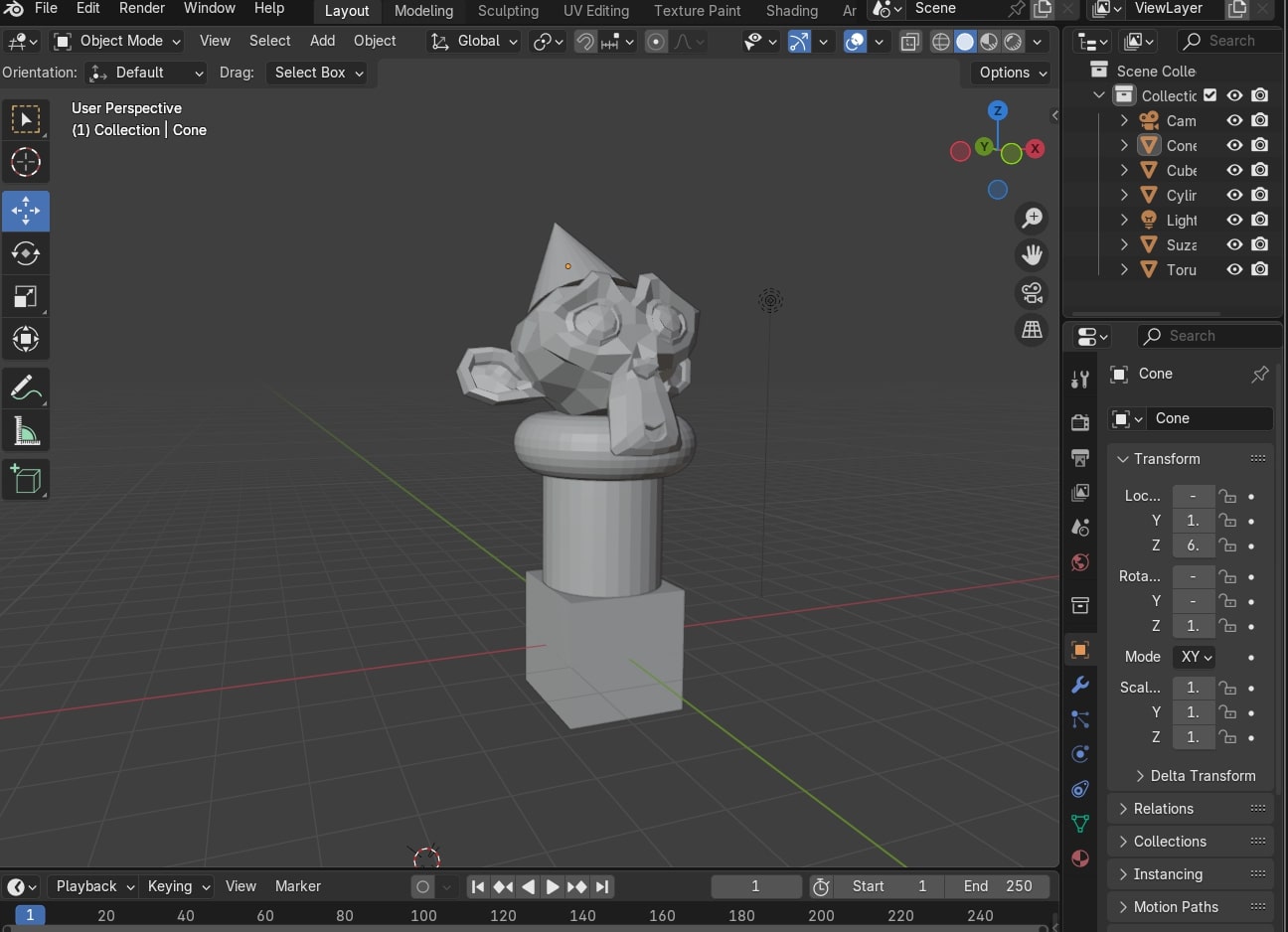
1: Main window - here you can change modes
2: Scene collection - shows all the elemnts, can change modes aswell
3: Buttons window - for adjusting settings
4: Keyframe control
x: Blender has a non overlapping windows policy
xx: Sidebar(left):
Tips:
1: Right after adding a mesh a panel will apear in the lower left screen, here adjustments can be made for the new mesh, but ONLY before you click away form the shape.
2:Always click ENTER!!
3: 1 Blender m = 1mm
4: Local view: Lest you look at and edit just 1 element
5: Shaders
right click + shape smooth
right click +  auto shape smooth --- treshhold angle smoothing
First we got familiar with the navigation system using the shortcuts G (Grab) to move objects around, R (rotate) to rotate an object and S (scale) to change the size of the elements. The result of this was a monkey tower.
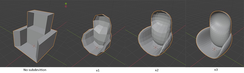
Using the shortcut E (extrude) I created a chair from a block. And with a modifier called subdevide I smoothened it out. this needs to be done in steps. Every time a subdevition is made the abount of parts doubles and if done too quickly or too many times this made my program crash.
Fusion intro from Saco at Waag Futulabs
Design principles and 3D modeling Steps:
Idea
List functional requrements
Make conceptual design - sketch by hand, write in words
Make a basic design and structure your mechanics, electronics and software -- block diagram
Engineering and detailed design (3D-models, schematics, ect.)
Build prototype or product
FBS -- Functional Breakdown Structure
What it does
(sub)functions
function combinations
requrements for functions
PBS -- Product Breakdown Structure
defining structure
definign parts
how it should be built
interfaces between parts
design stratgy for parts
risk asessments
work distribution in team
defining specifications for components
WBS -- Work Breakdown Structure
what has to be done
what is related
what is priority
3D-modeling
Before:
Make sketches on paper
Choose the right tool for the job
Use your PBS to set up the part structure
For each part: define the design strategy
About Fusion
Well used engineering CAD tool.
GOod for solids, but has other modes aswell such as mesh. Good for working with assemblies, parametric design, analeysis of motion and strenth, machining.
In Waag we use vcarve. In Fusion the gcode can be made in a different way.
Lots of tutorials on website
Add here image of opening site and point out the panels:
Show the elements: Timeline Filestructure and naming Sketching and constraints - adding dimentions Change parameters - lets you change the parameters you have already made Inspect - for measuring Write the mouse controls Split body Revolve Sweep Offset plane Loft - under create
Some research
I have a vauge idea of how I would like to do this project. However, I am no engineer and know little about gearsystems. I therefore watcghed this youtube video to get a better understanding of what gears might work for me.
Types of gears:
| Type | Speed | RPM | BenefitS | Minuses |
|---|---|---|---|---|
| Spur | low-medium speed | up to 3600 rpm | ||
| Helical | High speed applications | More quiet then spur gears | ||
| Bevel |
Talked with Saco for some guidence. He mentioned a few different ways my plan could be achieved. ANd I will show them below.
Aftre looking around a bit on the internet I found this 3D printable ball bearing by Christoph Laimer that I would like to adapt for my project. TO do so I start by following his tutorial to learn to build it in fusion sos I can make changes to the design once I have more of a feeling for the program. I will 3D print my test, but I think the final model will need to be milled on the CNC machine.
3D: FreeCAD