12: Machining week
Planning and prepping
After an introduction to machine building by Saco we sat down to brainstorm a bit:
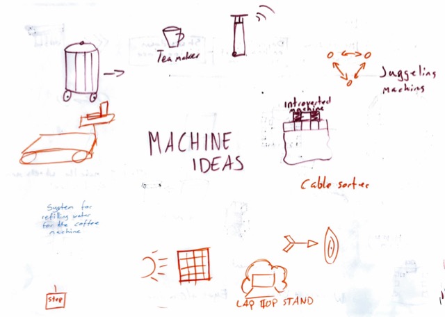
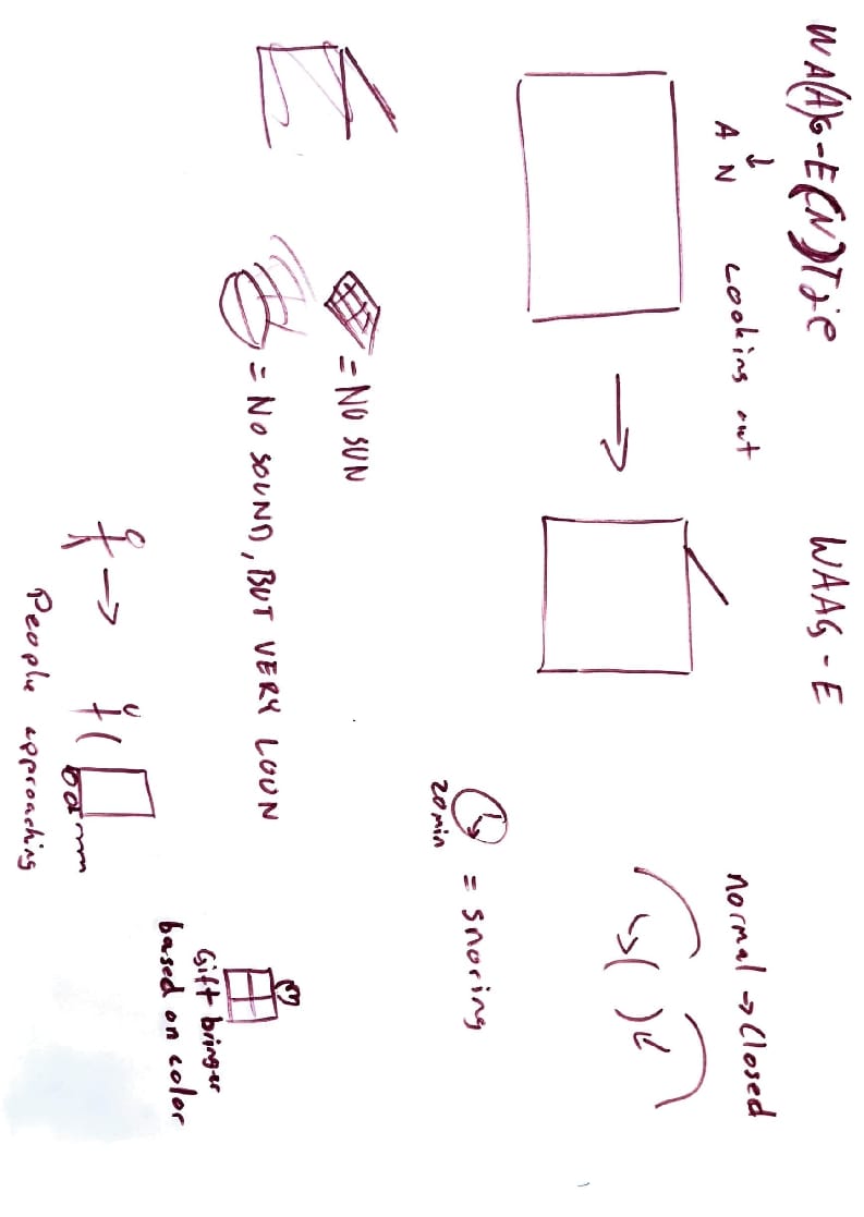
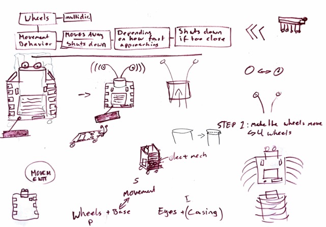
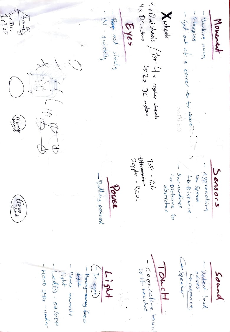
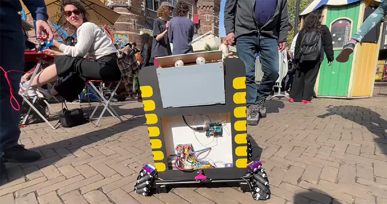
In conclution of this session we had decided to reuse some parts of the project from last week add link here and build a large version of a Xiao board, that shies away from people.
Spiral 1:
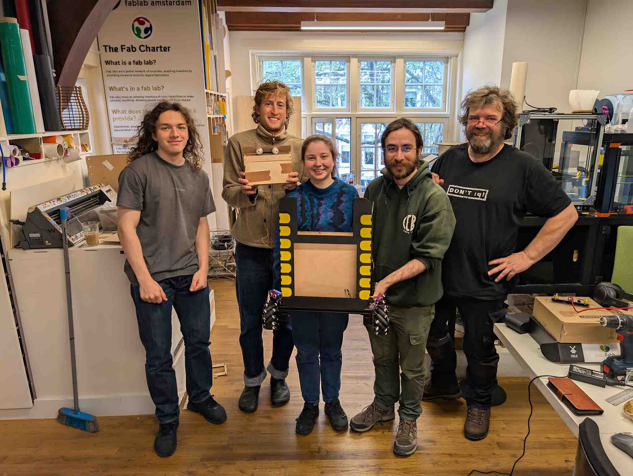
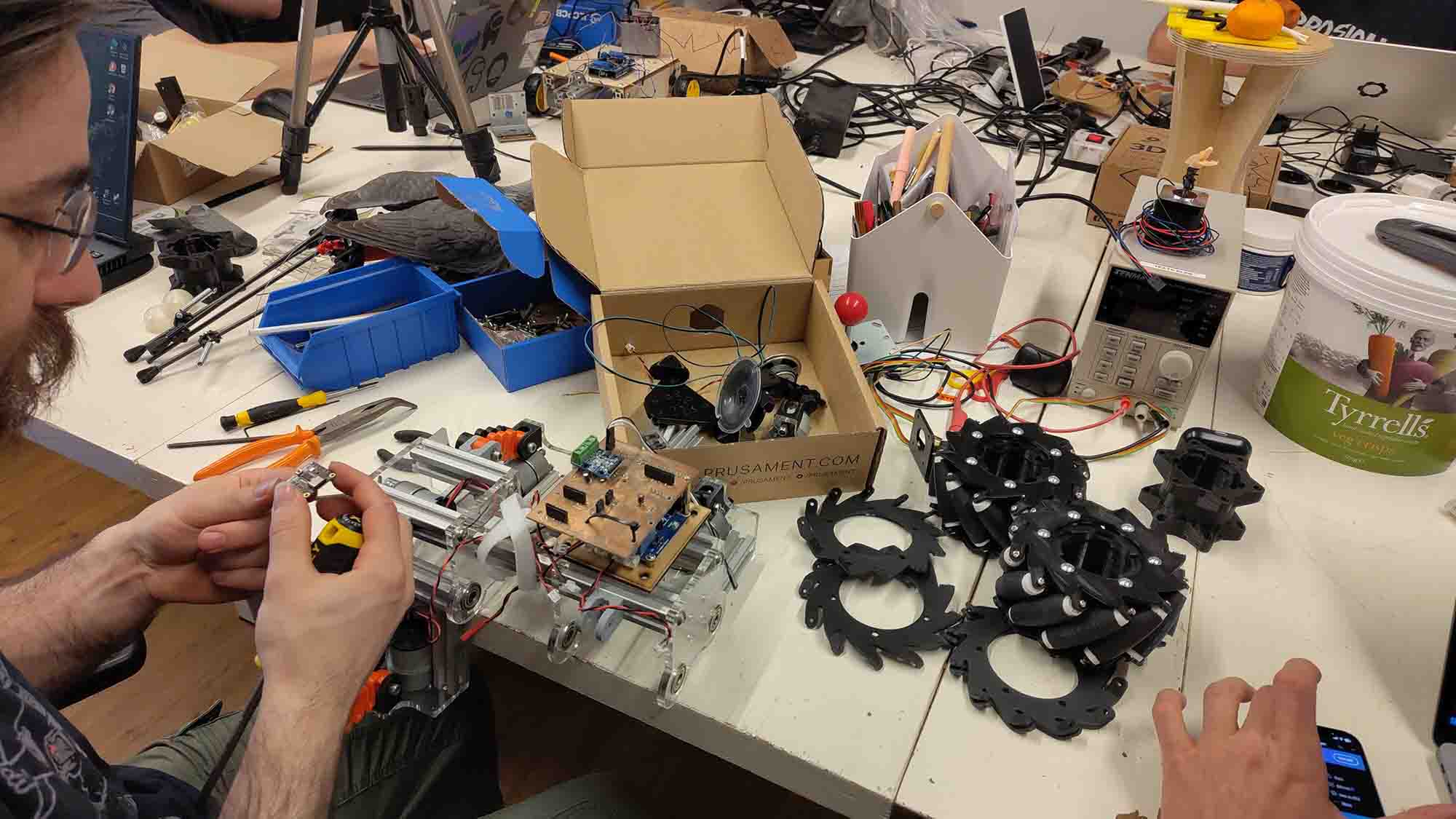
To begin with we split into 2. While Dylan and Sam worked on the sensors and coding, Patrick, who came up from Belgium for the machine week, and I started with the wheels and frame.
Tasks:
- Restoring wheels,
- make frame We checked the state of the wheels. For the Shy Xiao we want to reuse the omniwheels that where build last year link here. They did not get to use them in the end for their final video. First we had a look at what we were working with and what was missing. Patrick had brought with him some outer parts for the wheels from Belgium.
From what we could see we were missing:
- 1 x inner part of the wheel
- 2 outside parts
- 4x axels
Outer parts of the wheel
Link to website Thingiverse We were using this model to print the outer parts, but here the left outer holders had only 5 holes. We are using a modified inner part developed by the fabacademy students at Waag last year. This model has 6 holes. I therefore mirrored the model and printed it on the prusa.
Sadly, the prusa got clogged right at the end of the print and failed. insert image of failed print
This happened right at the end of the day, leaving no time to reprint it.
I therefore printed the parts at home and brought them in the next day:
image of green wheelholders
Inner part of the wheel
For the inner part of the wheel we used this model form the previous year and Sam printed it at home to save some time.
image of inner part
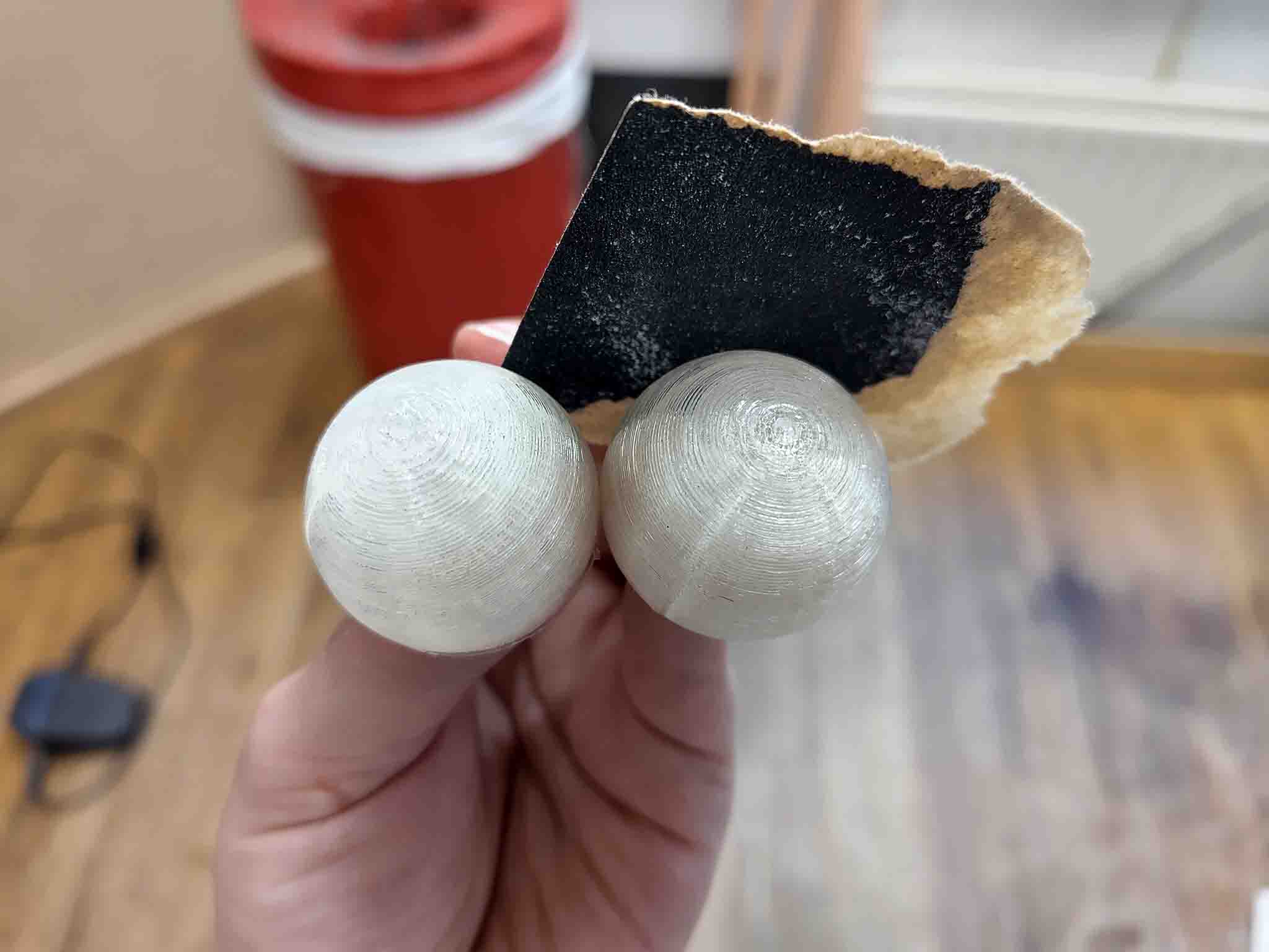
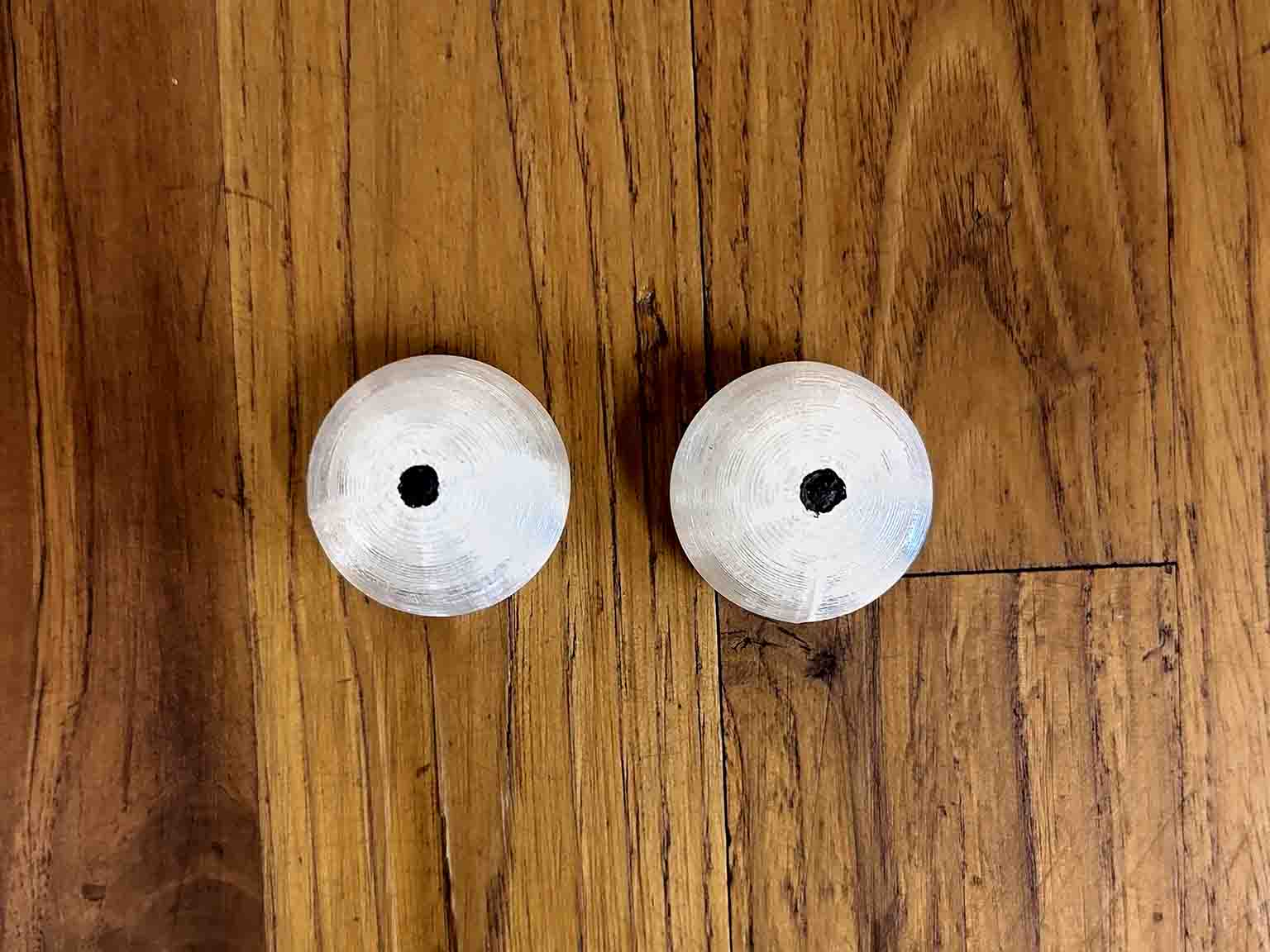
4x axels
link to Patricks site The old axels looked like they had been breaking. They had also been make for some DC motors. We wanted to switch to stepper motors, and Patrick modeled some new ones. Since the old ones had been breaking and were printed standing vertically, we decided to print the one ones laying horizontally.
On the first successful print the hole for the motor was too small
images
We were again running out of time and I printed some new ones at home:
imge here
Frame
For the frame for the wheels, Henk appeared with a big box of gifts:
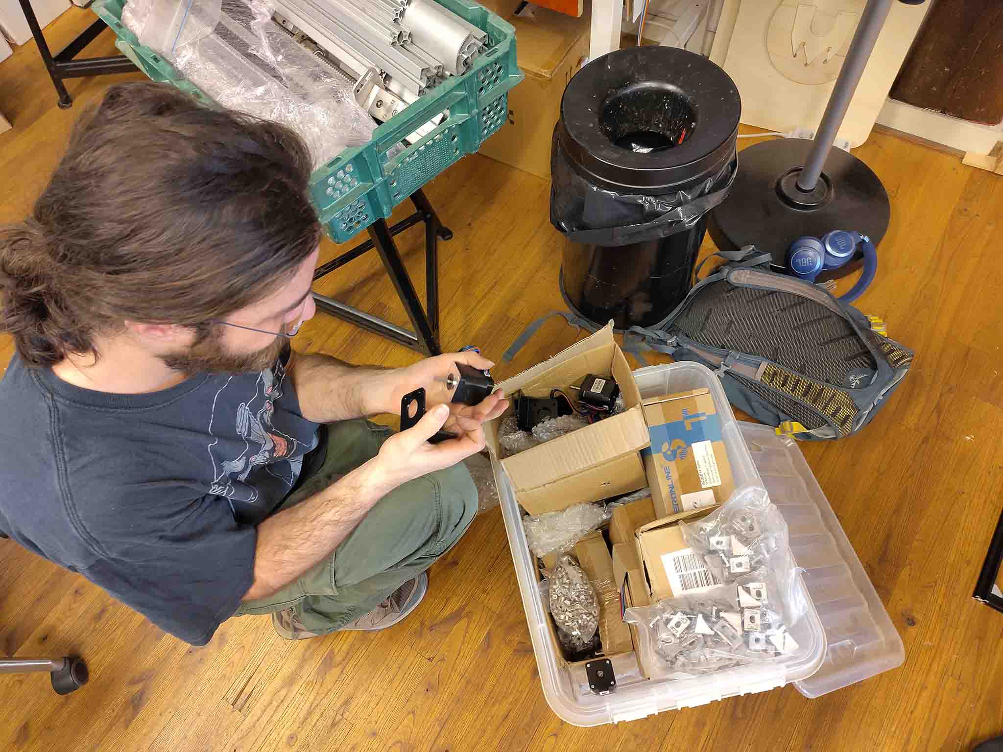
This contained lots of aluminium parts for the frame and stepper motors.
image sequence
With the wheels and assembled the first spiral was done and Dylan and Sam could make the base drive.
Spiral 2: Casing and Eyes
Front and eyes. Patrick has been working on the eye mechanism, and I have assisted him a bit, but my main focus was the body/casing of the XIAO.
Body
Eyes
For the body we want to display the electronics driving the wheels in a display case on the front. The original idea was to CNC pockets for this and for the parts where the pins connect, but this would add a lot of weight to the board. We have therefore decided to lasercut the casing.
Body
baseplate
Fisrat I modeled and lasercut a baseplate to screw into the base:
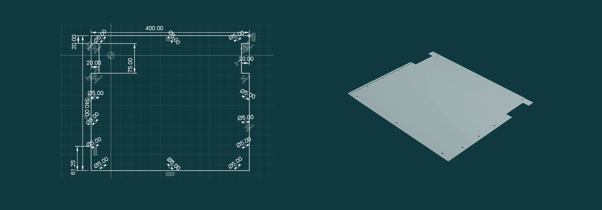
Turns out I added way too many holes. It only needed a few, but I think it will not be visible.
image of mounted baseplate
front
The plan is to create a pocket in the front between the front panel and the part where the support beams are places. We can slide in a piece between them.
illustration of plan for front pocket
THe electronics can then be mounted on that back wall:
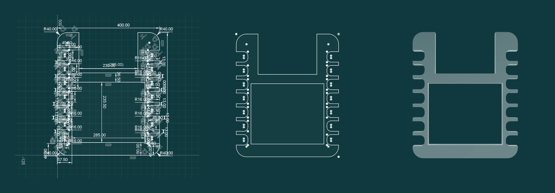
Illustration of electronics on back wall
And the 2 walls will serve as a holder for the USB port, containing the eyes, at the top.:
Illustration of board with USB port
Kerf calculation: Yellow plexi: power 50, speed 20, 3mm
Measurement: 98.06mm
After cutting: 100 - 98.06 = 1.94mm

1.94 mm/10 = 0.194mm kerf

In CAD softwares you offset by the radius of the kerf
0.194mm/2 = 0.097mm
Kerf calculation: wood: power 50, speed 20, 3.5mm
Measurement: 98.19mm
After cutting: 100 - 98.19 = 1.81mm

1.81 mm/10 = 0.181mm kerf

In CAD softwares you offset by the radius of the kerf
0.181mm/2 = 0.0905mm
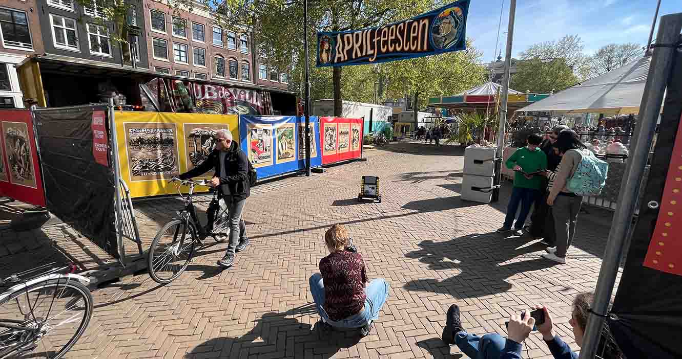
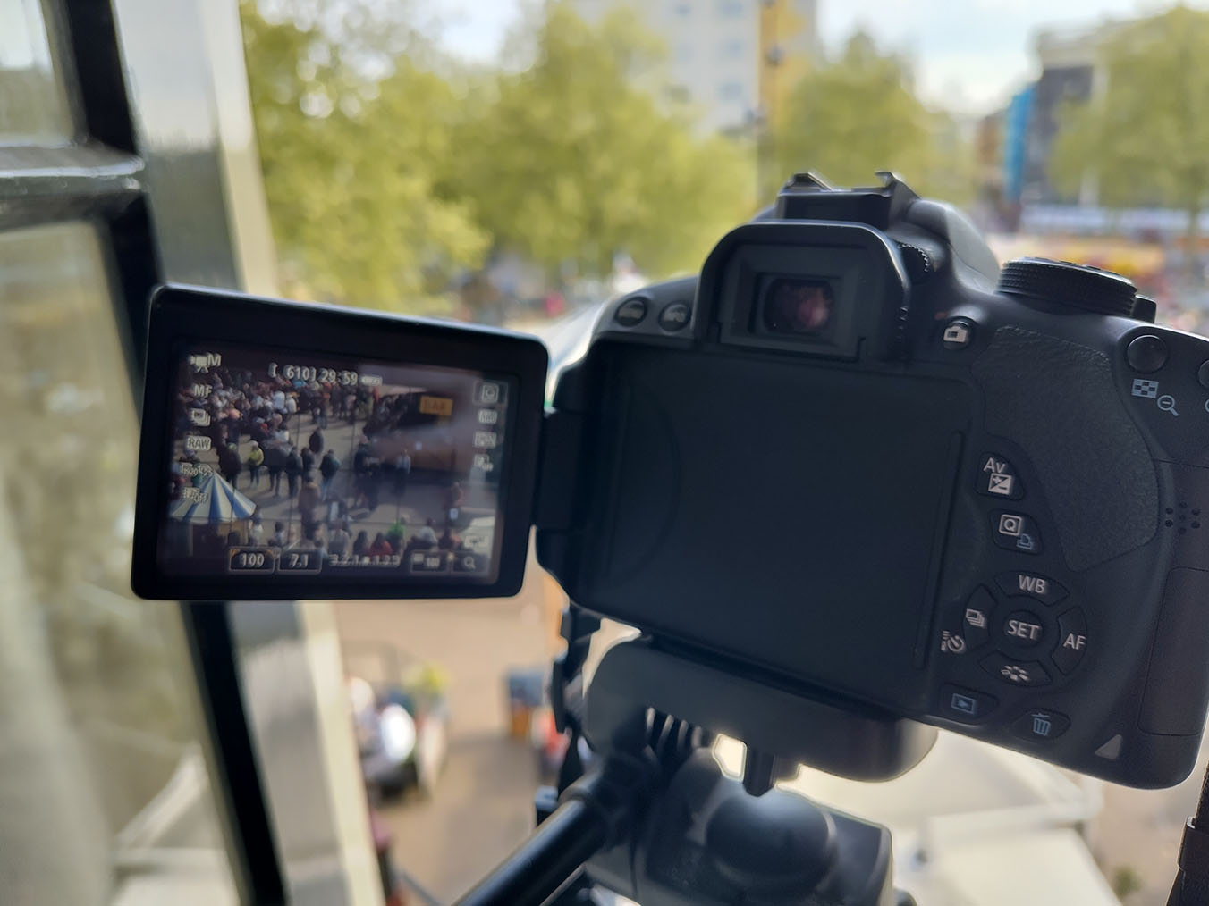
FILMING
Result: SHY XIAO / WAAG-E / WAAGENTJE