11: Networking and communication
Group assignment: Send a message between two projects
Individual: design, build, and connect wired or wireless node(s) with network or bus addresses and local input &/or output device(s)
I2C, microcontroller communication.
Group assignment
UTF8 converter
Notes from Niels lecture
Purposes: * Parallelism: multiple threads - allowing multiple programs to run at the same time * Modularity: scalability * Interference: Different voltages running in different parts of the system.
Wired * RS-232: processor and host * Peripherals: UART, USAT, SERCOM, PIO, bit-bang (write software) * Tx: sends * Rx: Recieves * How to separate signals: they are tristated. Hardcode adresses and code in when they switch form input to output to avoid problem with all the
Group assignment
I2C test with mine and Sams board from previous weeks.
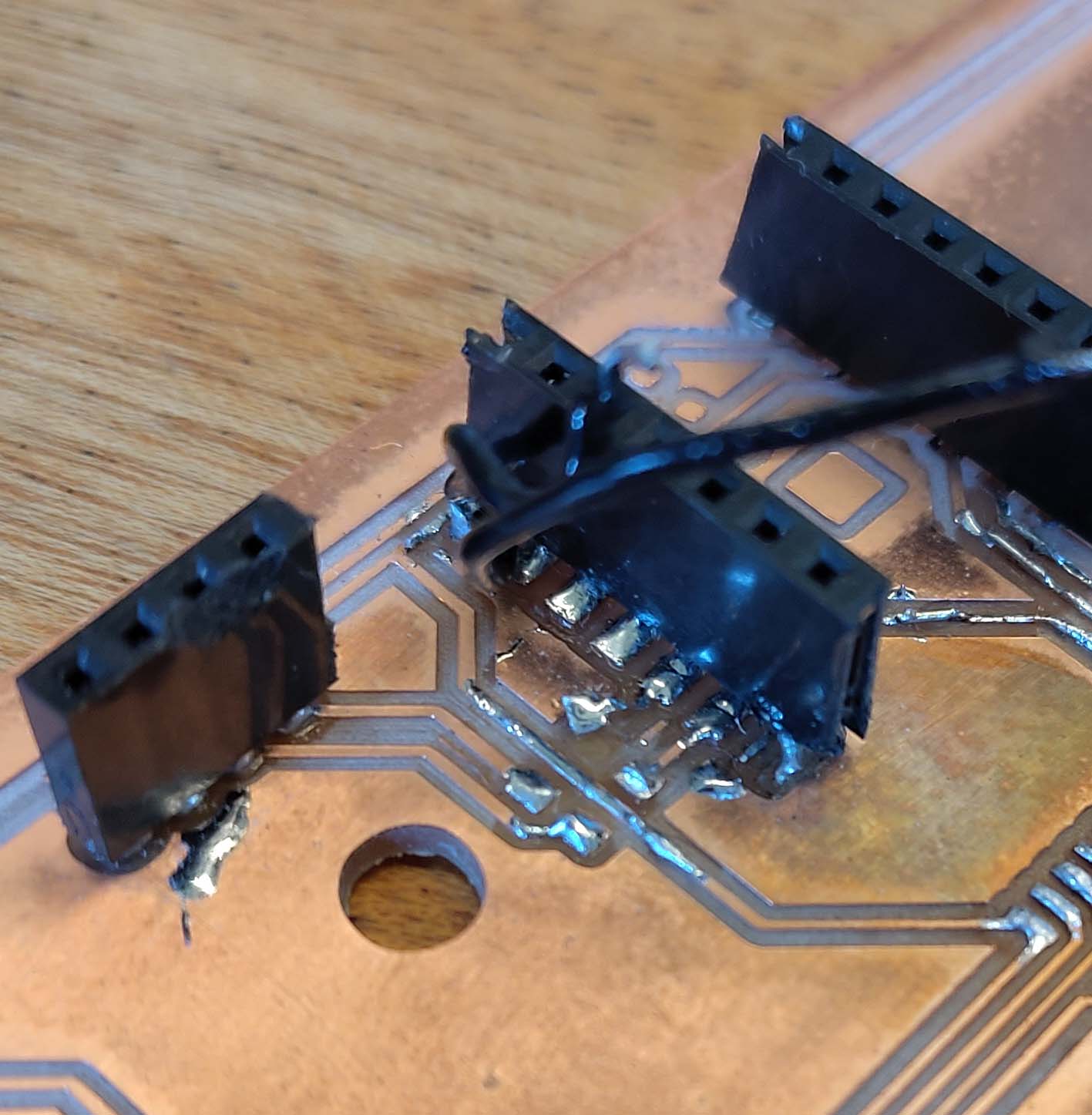
It was not working and that turned out to be because some of the wires on one of the boards had broken loose.
We tried it again with a xiao board connected through I2C and it worked.
We then attempted to connect through ESP NOW and that also worked! We used this website as a guide.
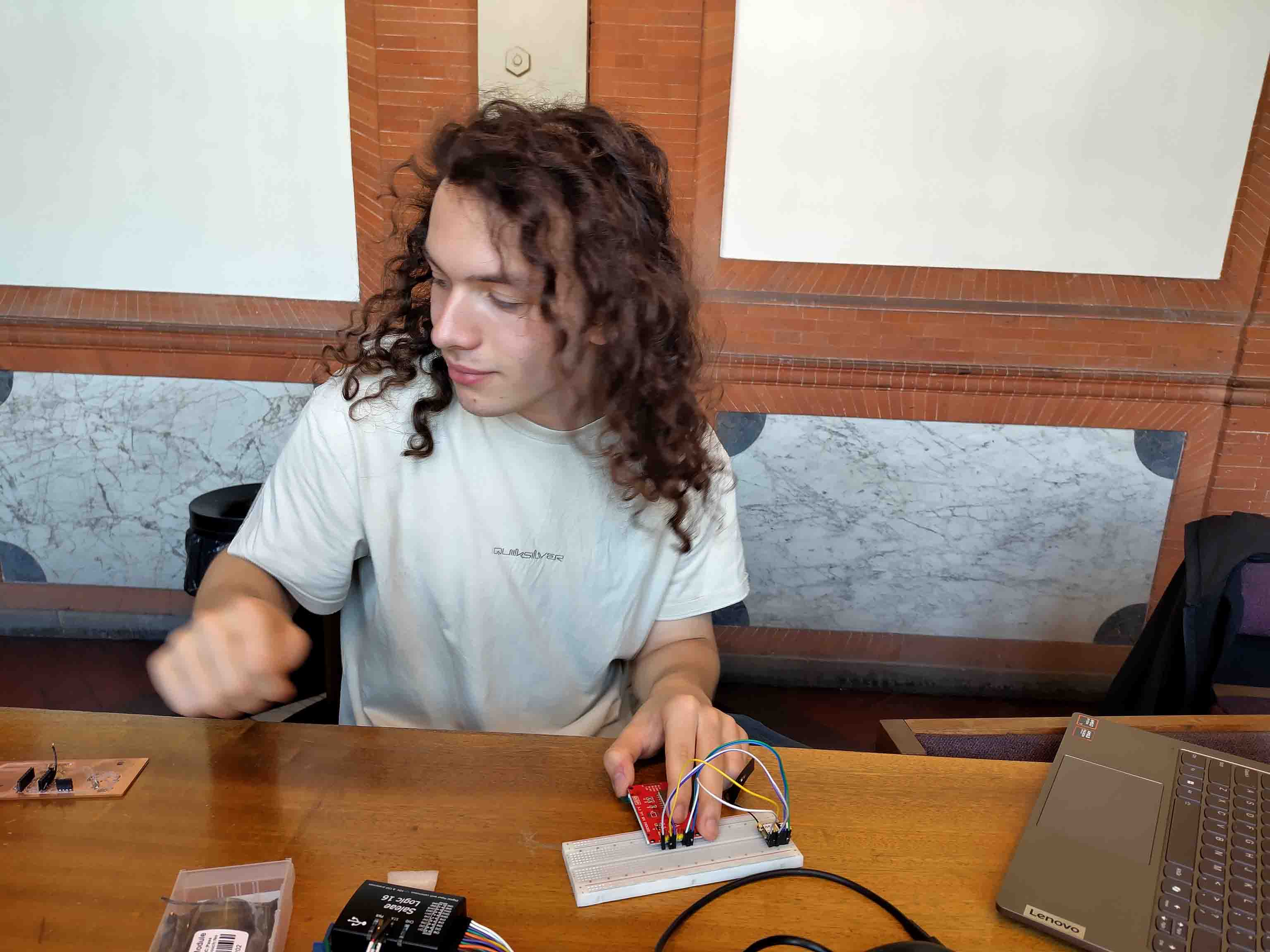
Here is a picture of Sam trying to make a screen work using SPI. It turned on but didn't work properly. I'm sure there is more about this in his documentation.
Individual assignment
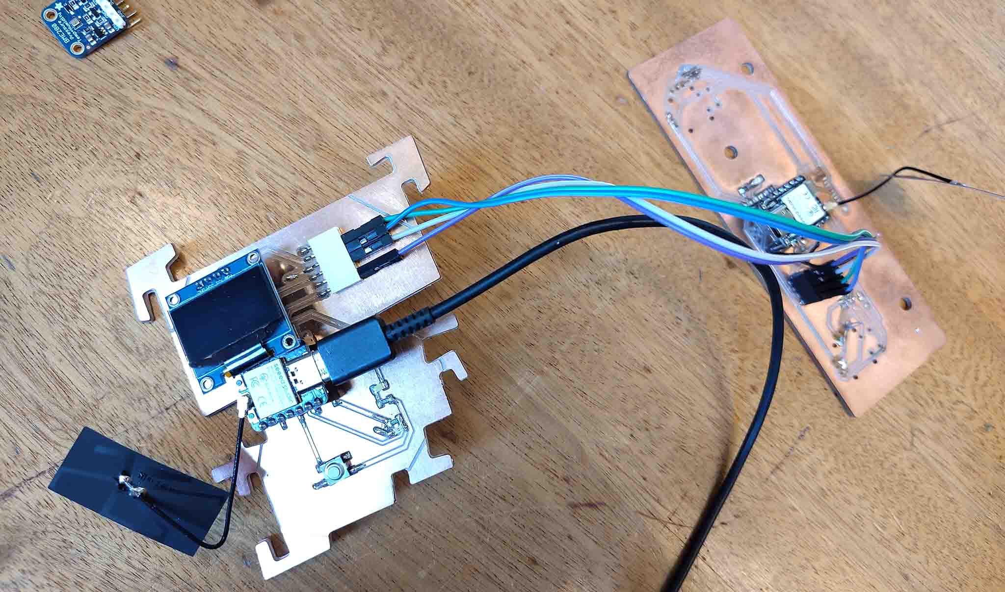
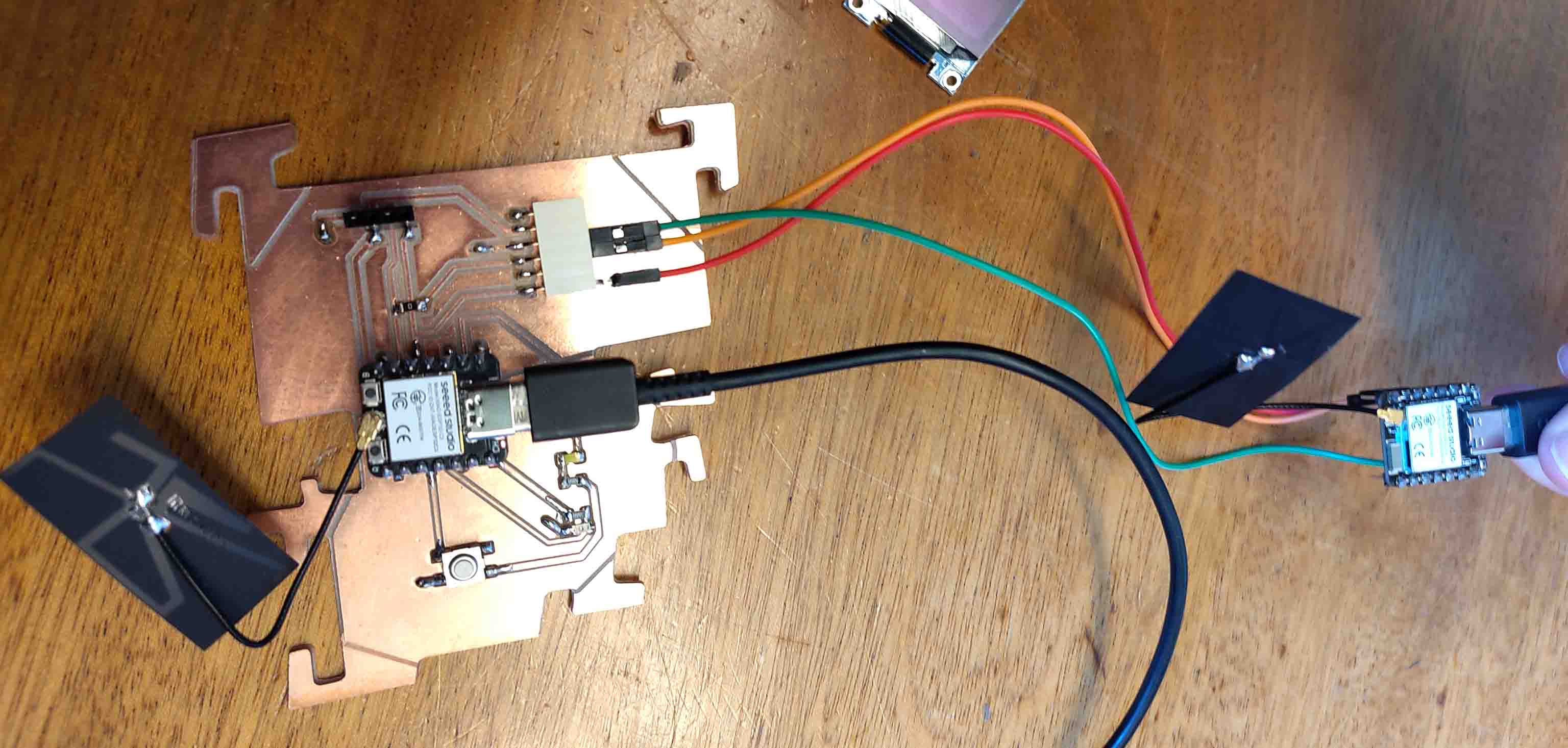
For my individual assignment this week I want to set up a wireless communication through ESP NOW between my Wall board (the board then will be on the wall with a BME280 Humidity sensor) and by touch board (has 3 touch pins for detecting water in the humidifier of my final project).
ESP NOW
The first step is to set up an ESP Now connection, but before that I need to understand what that is and how it works.
ESP-NOW supports the following features: (notes from Niels lecture)
- Encrypted and unencrypted unicast communication;
- Mixed encrypted and unencrypted peer devices;
- Up to 250-byte payload can be carried;
- Sending callback function that can be set to inform the application layer of transmission success or failure.
It is a wireless communications protocol developed by Espressif. It eabled multiple devices to send small messages (up to 250-bytes) to each other without using wifi.
The devices first needs to be paired before the they can send each other messages. If one of the devices is powered up, it will still reconnect when the power is switched on again. This is practical because the devices do not need to be re-paired every time they are restarted.
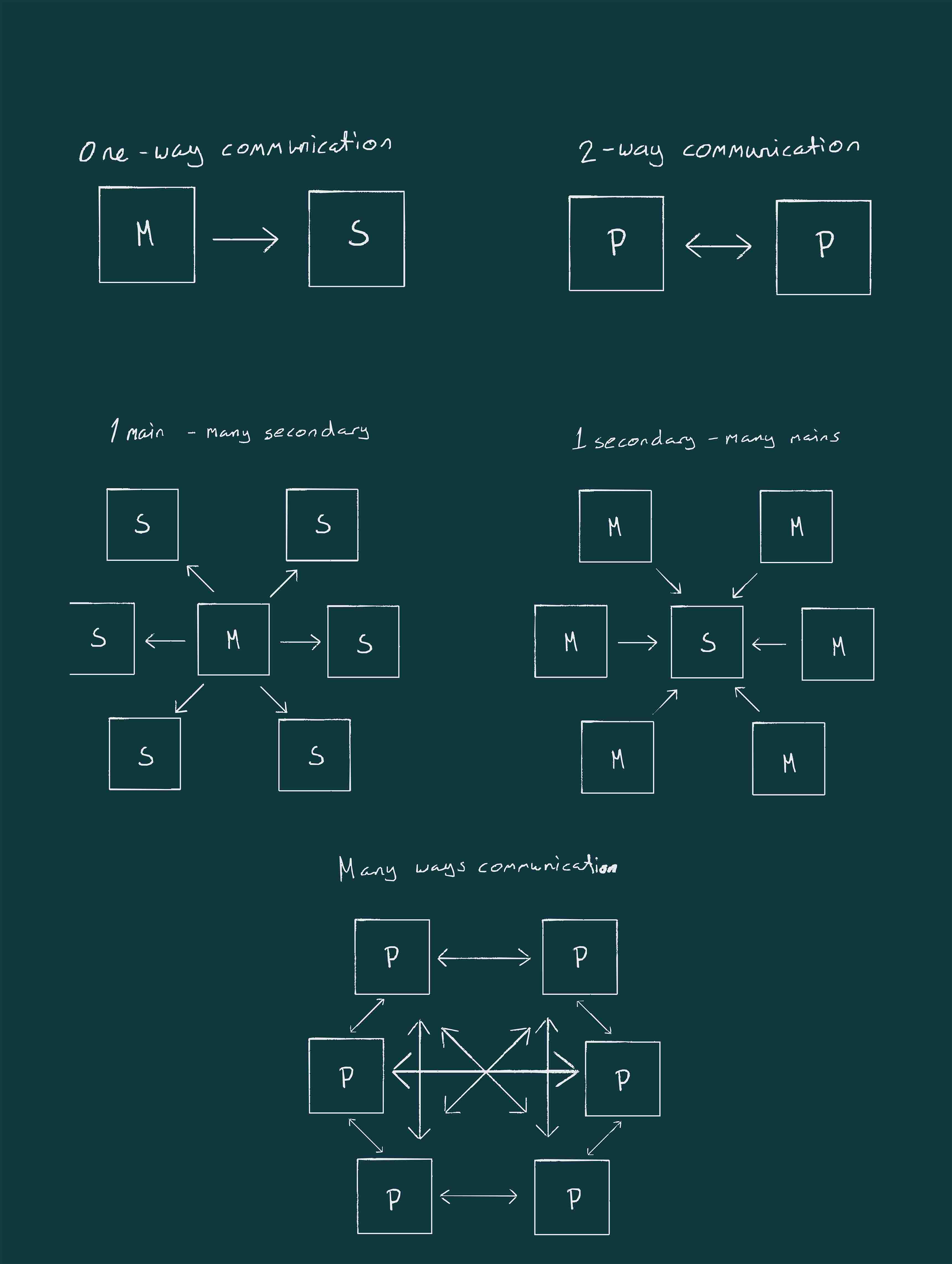
Communications
There are a few different communications that can be done with ESP NOW:
Mac adresses:
In order to communicate through ESP NOW the boards use Mac Adresses. Each board has a unique Mac Adress
To check the mac adresses of my boards I use this code:
#include "WiFi.h"       //To access ESP32 WIFI capabilities

void setup(){
    Serial.begin(115200);
    Serial.print("ESP32 Board MAC Address:  ");
    Serial.println(WiFi.macAddress());  //prints its MAC Address
    }
void loop(){}
My adresses:
- Wall board:
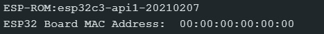 That can't be right.
I forgot WiFi.begin();
The functioning code is this:
#include "WiFi.h"       //To access ESP32 WIFI capabilities

void setup(){
    WiFi.begin();
    Serial.begin(115200);
    Serial.print("ESP32 Board MAC Address:  ");
    Serial.println(WiFi.macAddress());  //prints its MAC Address
}
void loop(){}
My MAC-addresses:
Wroom board:C4:DE:E2:20:EB:68Wall board:D4:F9:8D:03:6D:30Touch board:24:EC:4A:00:4A:DC
I can connect the Touch Board and Wall board through ESP NOW, but it is not working with the Wroom board. I am not sure why, but I will not be using that board.
Sending Data
In order to send data there are a few steps that needs to be followed:
- 1: Initialize ESP NOW
- 2: Register a callback function upon sending data: (OnDataSent);
- 3: Add a peer device: The receiver. Add the MAC address.
- 4: send a message to the peer device.
Receiving data:
In order to receive data there are also some steps to follow:
- 1: Initialize ESP NOW
- 2: Register for receive callback: function: (OnDataRecv);
- 3: Inside the callback function: Save the message into a variable.
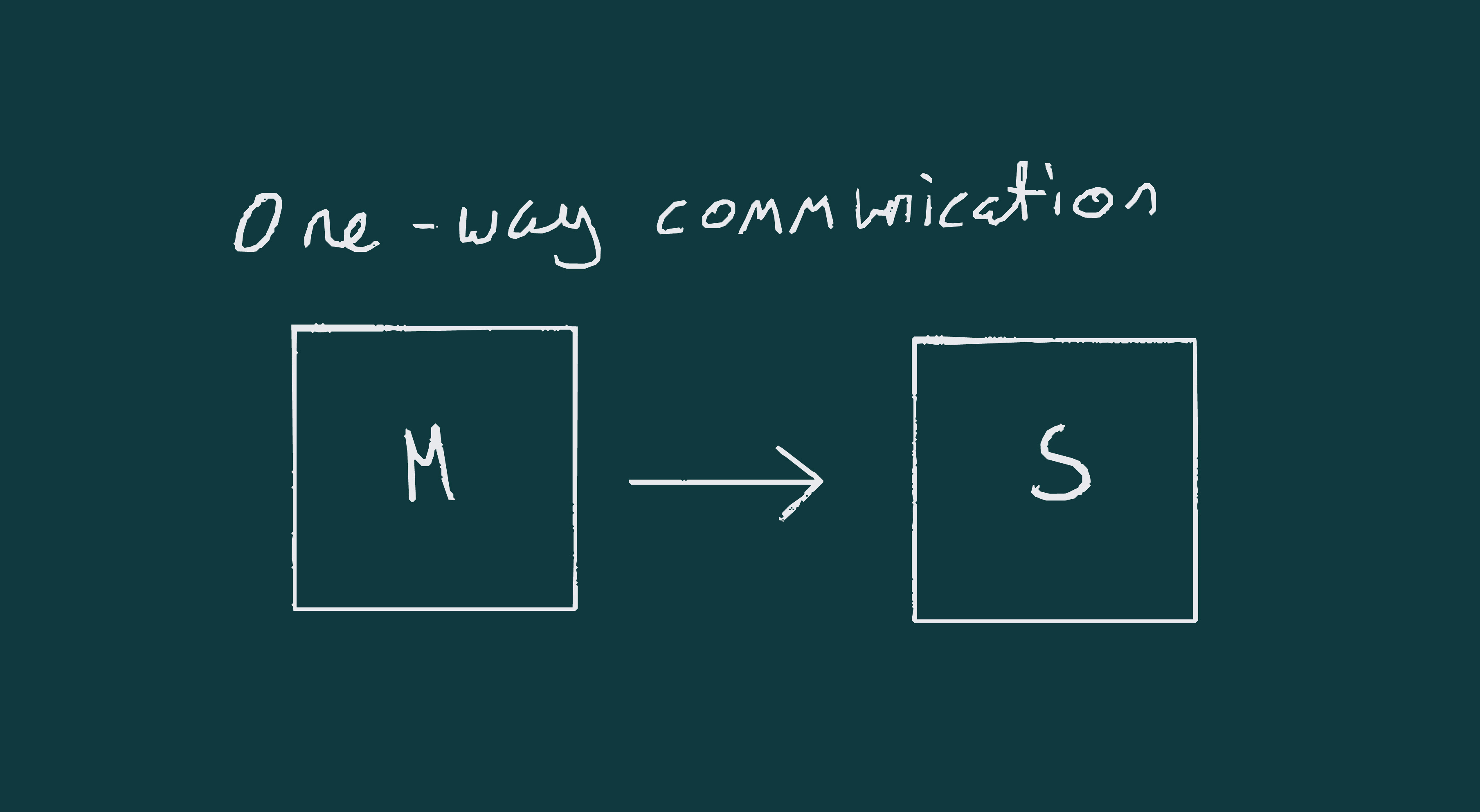
First connection:
First I will establish the connection between my 2 boards using 1-way communication:
For the transitter board I used this example code code:
/*
Rui Santos & Sara Santos - Random Nerd Tutorials
Complete project details at https://RandomNerdTutorials.com/esp-now-esp32-arduino-ide/
Permission is hereby granted, free of charge, to any person obtaining a copy of this software and associated documentation files.
The above copyright notice and this permission notice shall be included in all copies or substantial portions of the Software.
*/
#include <esp_now.h>
#include <WiFi.h>
//* `Wall board:` D4:F9:8D:03:6D:30
//* `Touch board:` 24:EC:4A:00:4A:DC
uint8_t broadcastAddress[] = {0x24, 0xEC, 0x4A, 0x00, 0x4A, 0xDC}; // Touch board
// Structure example to send data
// Must match the receiver structure
typedef struct struct_message {
char a[32];
int b;
float c;
bool d;
} struct_message;
// Create a struct_message called myData
struct_message myData;
esp_now_peer_info_t peerInfo;
// callback when data is sent
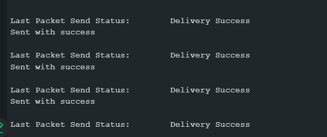
void OnDataSent(const uint8_t *mac_addr, esp_now_send_status_t status) {
Serial.print("\r\nLast Packet Send Status:\t");
Serial.println(status == ESP_NOW_SEND_SUCCESS ? "Delivery Success" : "Delivery Fail");
}
void setup() {
// Init Serial Monitor
Serial.begin(115200);
// Set device as a Wi-Fi Station
WiFi.mode(WIFI_STA);
// Init ESP-NOW
if (esp_now_init() != ESP_OK) {
Serial.println("Error initializing ESP-NOW");
return;
}
// Once ESPNow is successfully Init, we will register for Send CB to
// get the status of Trasnmitted packet
esp_now_register_send_cb(OnDataSent);
// Register peer
memcpy(peerInfo.peer_addr, broadcastAddress, 6);
peerInfo.channel = 0;
peerInfo.encrypt = false;
// Add peer
if (esp_now_add_peer(&peerInfo) != ESP_OK){
Serial.println("Failed to add peer");
return;
}
}
void loop() {
// Set values to send
strcpy(myData.a, "THIS IS A CHAR");
myData.b = random(1,20);
myData.c = 1.2;
myData.d = false;
// Send message via ESP-NOW
esp_err_t result = esp_now_send(broadcastAddress, (uint8_t *) &myData, sizeof(myData));
if (result == ESP_OK) {
Serial.println("Sent with success");
}
else {
Serial.println("Error sending the data");
}
delay(2000);
}
And this code for the receiver:
/*
Rui Santos & Sara Santos - Random Nerd Tutorials
Complete project details at https://RandomNerdTutorials.com/esp-now-esp32-arduino-ide/
Permission is hereby granted, free of charge, to any person obtaining a copy of this software and associated documentation files.
The above copyright notice and this permission notice shall be included in all copies or substantial portions of the Software.
*/
#include <esp_now.h>
#include <WiFi.h>
// Structure example to receive data
// Must match the sender structure
typedef struct struct_message {
char a[32];
int b;
float c;
bool d;
} struct_message;
// Create a struct_message called myData
struct_message myData;
// callback function that will be executed when data is received
void OnDataRecv(const uint8_t * mac, const uint8_t *incomingData, int len) {
memcpy(&myData, incomingData, sizeof(myData));
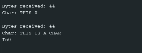
Serial.print("Bytes received: ");
Serial.println(len);
Serial.print("Char: ");
Serial.println(myData.a);
Serial.print("Int: ");
Serial.println(myData.b);
Serial.print("Float: ");
Serial.println(myData.c);
Serial.print("Bool: ");
Serial.println(myData.d);
Serial.println();
}
void setup() {
// Initialize Serial Monitor
Serial.begin(115200);
// Set device as a Wi-Fi Station
WiFi.mode(WIFI_STA);
// Init ESP-NOW
if (esp_now_init() != ESP_OK) {
Serial.println("Error initializing ESP-NOW");
return;
}
// Once ESPNow is successfully Init, we will register for recv CB to
// get recv packer info
esp_now_register_recv_cb(esp_now_recv_cb_t(OnDataRecv));
}
void loop() {
}
As seen in the image below the communication worked:

Altering the example code
In the struct messages I changed all the values for sending to ints. because I will be sending numbers:
typedef struct struct_message {
    int a;
    int b;
    int c;
} struct_message;
In the transmitter code/ main code, in the loop i changed the myData readings to be the values of the touchPins on the board:
myData.a = touchRead(3);
myData.b = touchRead(4);
myData.c = touchRead(8);
And in the reciever / secondary code I changed the serial prints to display the values of the touchPins:
void OnDataRecv(const uint8_t * mac, const uint8_t *incomingData, int len) {
    memcpy(&myData, incomingData, sizeof(myData));
    Serial.print("Bytes received: ");
    Serial.println(len);
    Serial.print("Touch 1: ");
    Serial.println(myData.a);
    Serial.print("Touch 2: ");
    Serial.println(myData.b);
    Serial.print("Touch 3: ");
    Serial.println(myData.c);
}
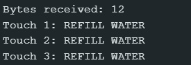
Here is a screenshot from the Serial Monitors.
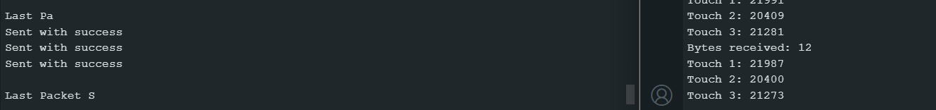
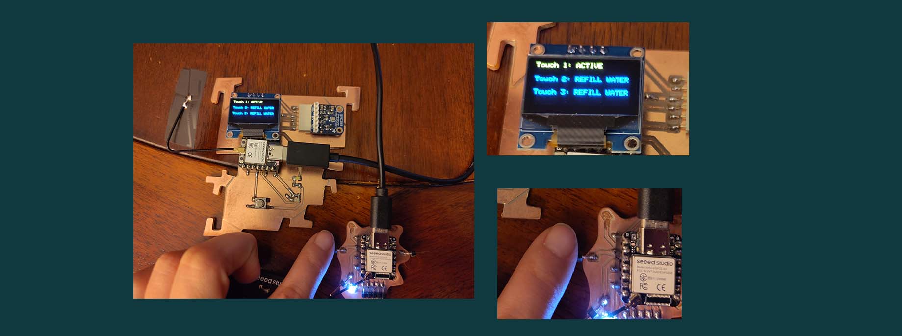
The numbers in themselves are not very understandable. I therefore altered the code to tell if the pins are active: meaning that there is water touching the pin or REFILL WATER. Meaning there is no water touching the pin. I will use this as a safety mechanism for the ultrasonic atomizers not to get switched on if the container is empty. As this would break them.
Now that I have the values sent from the touch board I wanted to display them on the wall board. To do this I combined the code I have from before (the one used for displaying humidity).
I changed the On DataRecieved() function to first clear the display:
display.clearDisplay();
And then I moved all of the touch values into 1 function:
void Touch_1(){
    if (myData.a < 30000){
        display.setTextSize(1);
        display.setTextColor(WHITE); // needs to be here
        display.setCursor(0,0);
        display.print("Touch 1: REFILL WATER");
        display.display();
    } else {
        display.setTextSize(1);
        display.setTextColor(WHITE); // needs to be here
        display.setCursor(0,0);
        display.print("Touch 1: ACTIVE");
        display.display();
    }

    if (myData.b < 30000){
        display.setTextSize(1);
        display.setTextColor(WHITE); // needs to be here
        display.setCursor(0,20);
        display.print("Touch 2: REFILL WATER");
        display.display();
    } else {
        display.setTextSize(1);
        display.setTextColor(WHITE); // needs to be here
        display.setCursor(0,20);
        display.print("Touch 2: ACTIVE");
        display.display();
    }

    if (myData.c < 30000){
        display.setTextSize(1);
        display.setTextColor(WHITE); // needs to be here
        display.setCursor(0,40);
        display.print("Touch 3: REFILL WATER");
        display.display();
    } else {
        display.setTextSize(1);
        display.setTextColor(WHITE); // needs to be here
        display.setCursor(0,40);
        display.print("Touch 3: ACTIVE");
        display.display();
    }
delay(10);
}
OnDataRecieved() calls this function after clearing the display. The whole function looks like this:
void OnDataRecv(const uint8_t * mac, const uint8_t *incomingData, int len) {
    memcpy(&myData, incomingData, sizeof(myData));
    Serial.print("Bytes received: ");
    Serial.println(len);
    display.clearDisplay();
    Touch_1();
}
Here is the result:
And here is the full code:
// this sketch recieves the touch values and translates them from numbers to: ACTIV or REFILL WATER
// And puts them on a display
#include <esp_now.h>
#include <WiFi.h>

#include <Adafruit_GFX.h>
#include <Adafruit_SSD1306.h>

#define SCREEN_WIDTH 128 // OLED display width, in pixels
#define SCREEN_HEIGHT 64 // OLED display height, in pixels

#define OLED_RESET     -1 // Reset pin # (or -1 if sharing Arduino reset pin)
#define SCREEN_ADDRESS 0x3C ///< See datasheet for Address; 0x3D for 128x64, 0x3C for 128x32
Adafruit_SSD1306 display(SCREEN_WIDTH, SCREEN_HEIGHT, &Wire, OLED_RESET);

#define NUMFLAKES     10 // Number of snowflakes in the animation example

#define LOGO_HEIGHT   16
#define LOGO_WIDTH    16


// Structure example to receive data
// Must match the sender structure
typedef struct struct_message {
    int a;
    int b;
    int c;
} struct_message;

// Create a struct_message called myData
struct_message myData;

// callback function that will be executed when data is received
void OnDataRecv(const uint8_t * mac, const uint8_t *incomingData, int len) {
memcpy(&myData, incomingData, sizeof(myData));
Serial.print("Bytes received: ");
Serial.println(len);
display.clearDisplay();
Touch_1();
}

void setup() {
// Initialize Serial Monitor
Serial.begin(115200);

if(!display.begin(SSD1306_SWITCHCAPVCC, SCREEN_ADDRESS)) {
    Serial.println(F("SSD1306 allocation failed"));
    for(;;); // Don't proceed, loop forever
}

display.display();
delay(2000); // Pause for 2 seconds

// Clear the buffer
display.clearDisplay();

// Draw a single pixel in white
display.drawPixel(10, 10, SSD1306_WHITE);

// Set device as a Wi-Fi Station
WiFi.mode(WIFI_STA);

// Init ESP-NOW
if (esp_now_init() != ESP_OK) {
    Serial.println("Error initializing ESP-NOW");
    return;
}

// Once ESPNow is successfully Init, we will register for recv CB to
// get recv packer info
esp_now_register_recv_cb(esp_now_recv_cb_t(OnDataRecv));
}

void loop() {

}

void Touch_1(){
if (myData.a < 30000){
    display.setTextSize(1);
    display.setTextColor(WHITE); // needs to be here
    display.setCursor(0,0);
    display.print("Touch 1: REFILL WATER");
    display.display();
} else {
    display.setTextSize(1);
    display.setTextColor(WHITE); // needs to be here
    display.setCursor(0,0);
    display.print("Touch 1: ACTIVE");
    display.display();
}

if (myData.b < 30000){
    display.setTextSize(1);
    display.setTextColor(WHITE); // needs to be here
    display.setCursor(0,20);
    display.print("Touch 2: REFILL WATER");
    display.display();
} else {
    display.setTextSize(1);
    display.setTextColor(WHITE); // needs to be here
    display.setCursor(0,20);
    display.print("Touch 2: ACTIVE");
    display.display();
}

if (myData.c < 30000){
    display.setTextSize(1);
    display.setTextColor(WHITE); // needs to be here
    display.setCursor(0,40);
    display.print("Touch 3: REFILL WATER");
    display.display();
} else {
    display.setTextSize(1);
    display.setTextColor(WHITE); // needs to be here
    display.setCursor(0,40);
    display.print("Touch 3: ACTIVE");
    display.display();
}
delay(10);
}
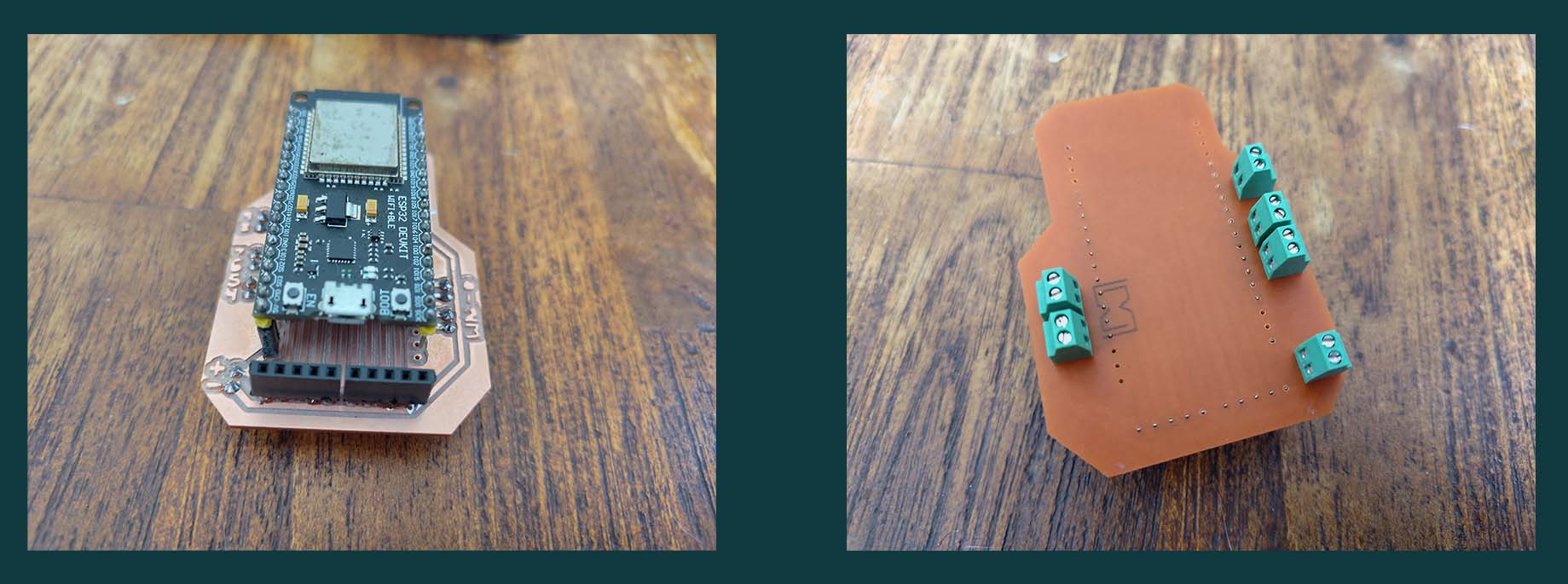
New board for personal project
I want to connect more touch pins and a few relays. In order to do this I need more pins. At home I had a ESP Wroom-32 board with 38 pins laying around. KiCad did not have the right footprint for this. Sam showed me that I could find the board, or at least a similar one in DigiKey and download the KiCAD footprint from there:
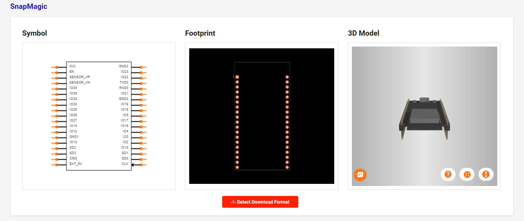
I imported the _sym file into symbols from the schematics editor and in the PCB editor I added the new footprint to footprints, just like when adding the FAB library. Documentation for this can be found in electronics design.
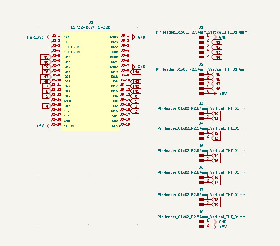
I want to use screw terminals fort the touch wires. These are named T0 -T9. I only need 8, but have added the 2 extra in case I want to upscale to more containers or possibly add an interaction with it through capacative touch. It seemed a shame to not make all the 10 touchpins usable.
The pins going to the relay module are named IN1 - IN9.
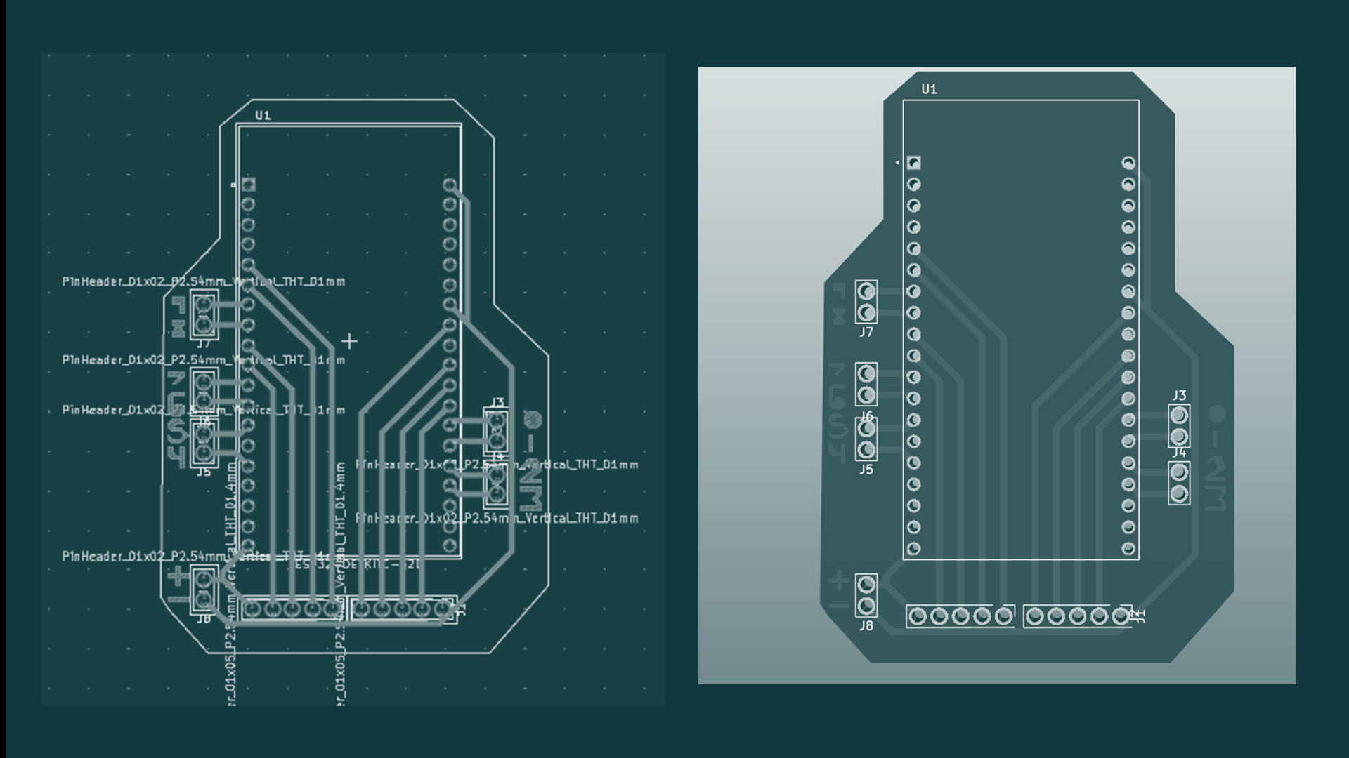
Here is the PCB layout. The holes are not all the same and also not the same size as the drilling bit I was using, so had to change them to be .8 mm.
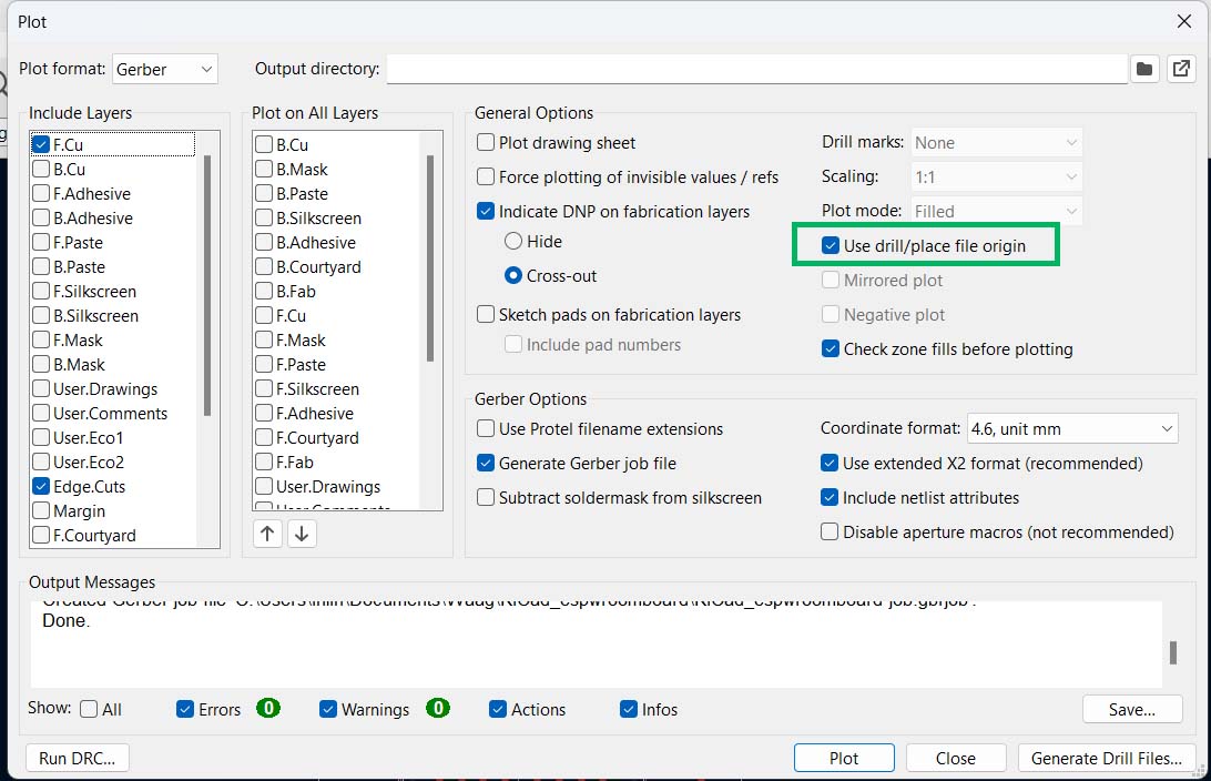
When I first exported the gerber files they were mising the drillign files, so just for a remined, be sure to check this box:
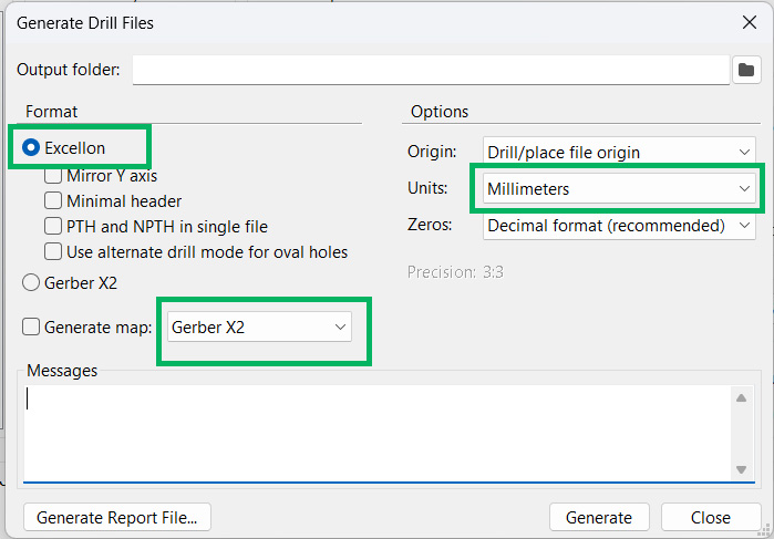
And make sure to export the files as Exellion, Germer X2 and doucble check that they are in millimeters.
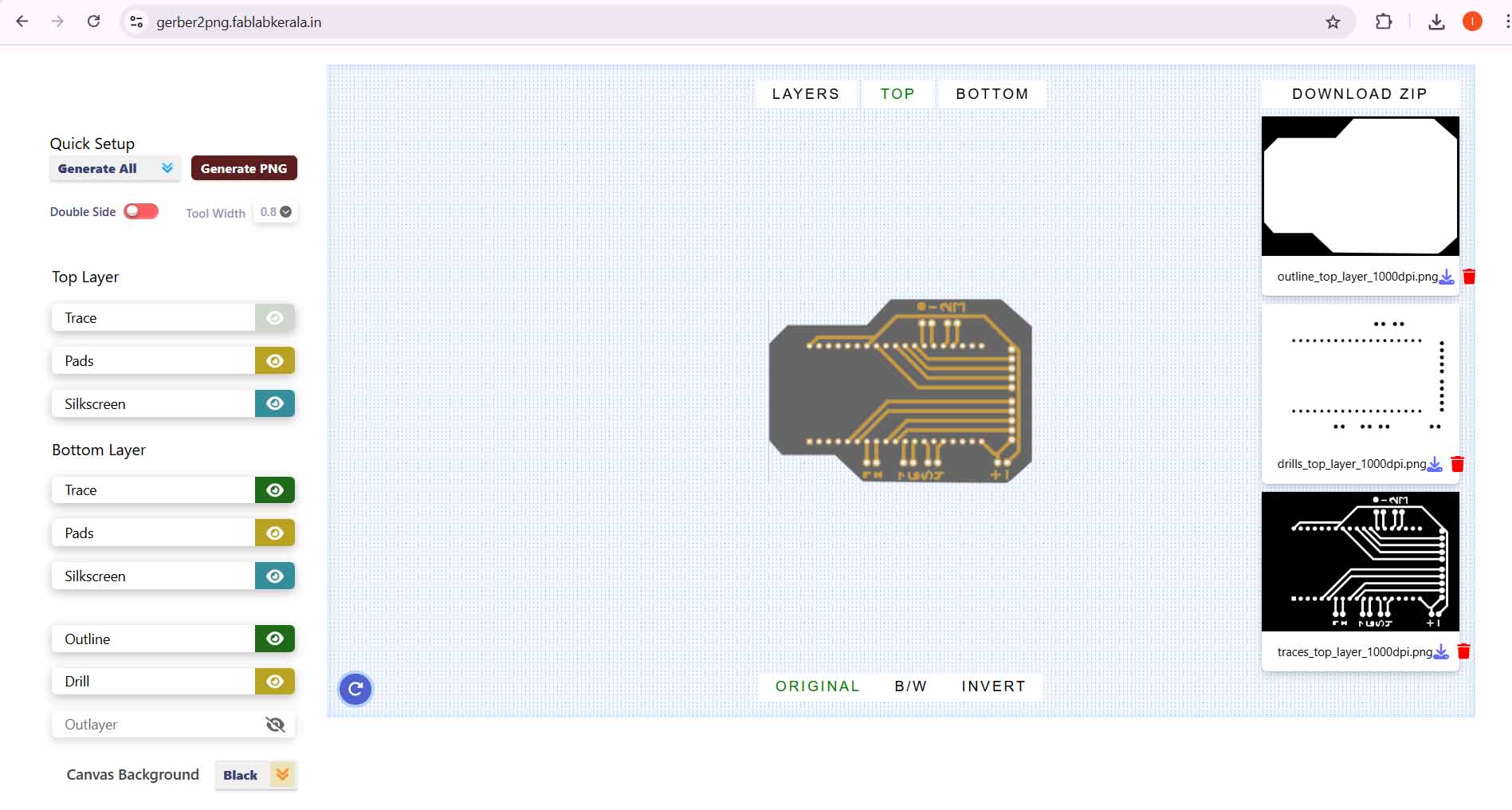
This time I put the fines into Fablab Kerala Gerber2PNG converter. It was very simple. Just make sure to choose generate all in quick set up.
When milling the board I noticed that the bit was etching the back middle part of the PCB. I though that was a bit weird, until i realised that I had forgotten to tichten the screws when attaching the plate!
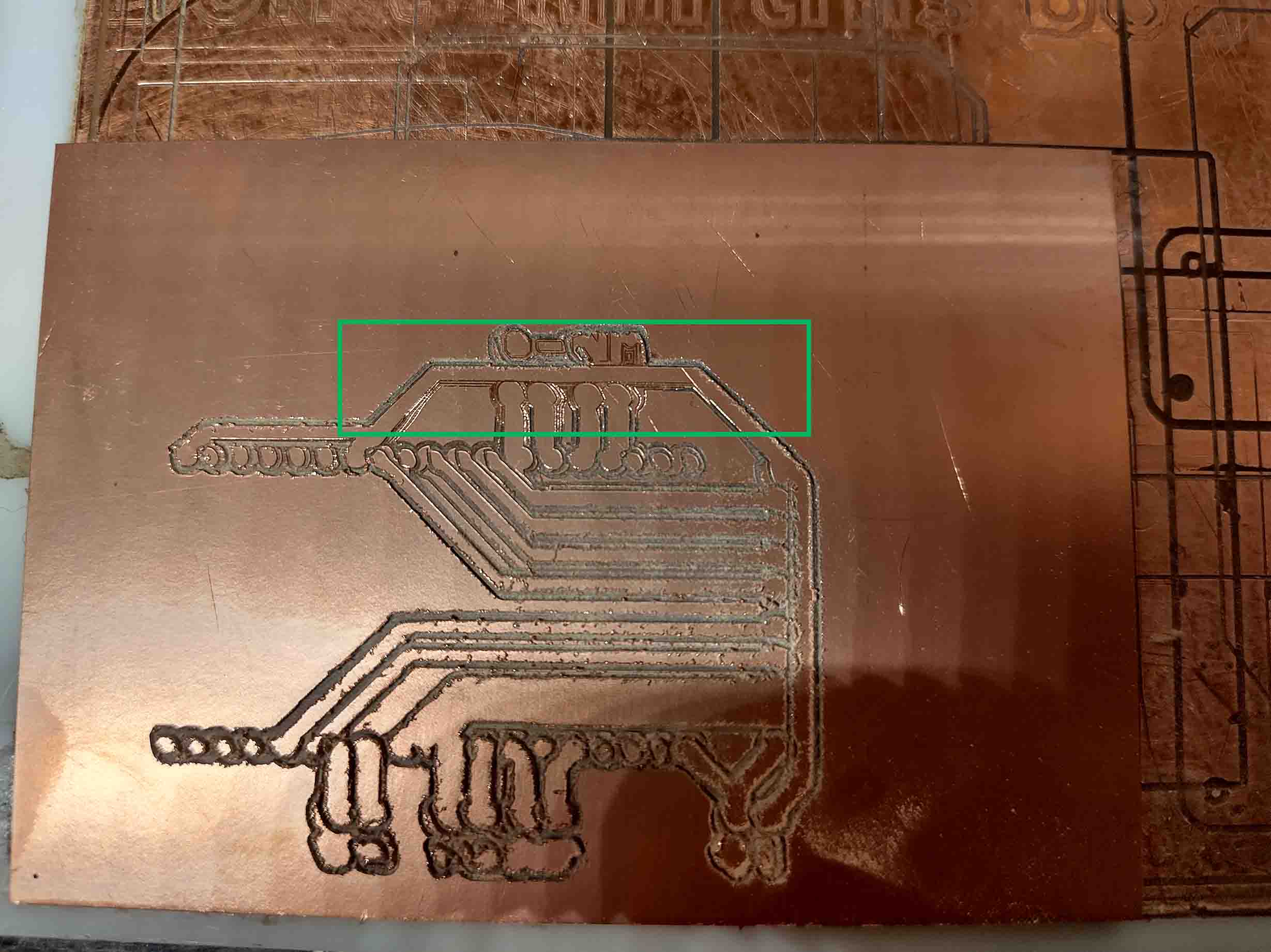
After attaching the plate properly and Z-leveling again I got back to it and here is the finished board.
Notes from Erwins slides
Given by Henk. These are my notes from the presentation. The slides can, as always, be found on Erwins fabacademy page.
Today we will: Use Logic Analyser to make the invisible communication visible.
Connecting stuff
Connecting stuff is to get data from here to there and back again.
From (lots of) sensors to microcontrollers to display. Using SPI or I2C. There is a small MCU on the back of these boards.
In FabAcademy networking often 1 main (µC(microcontroller)) and multiple secondaries (sensors, LEDs, displays).
Star topology
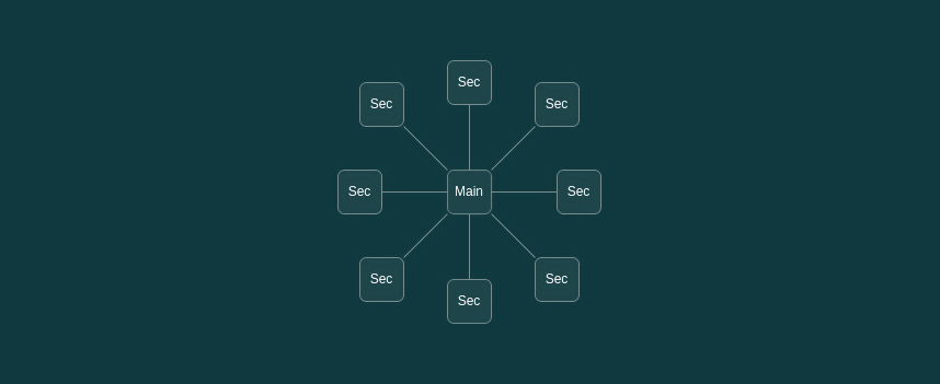 Can be done in a Star topology. This Main has 1:1 connection to all secondaries. Addressing is done by selecting a communication line. This is UART and SPI. No need for adresses illustration
Ring topology
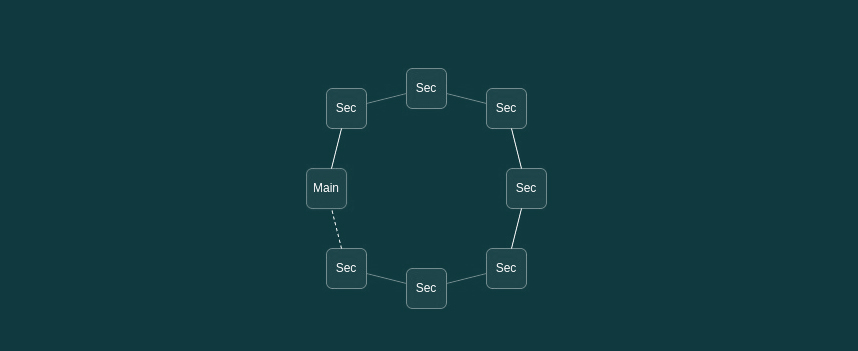 Another one is Ring topology. Output of one secondary is connected to the input of the next secondary. Addressing is done by its place in the ring. Examples of this are: neopixel and SPI. No need for adresses illustrations
Bus topology
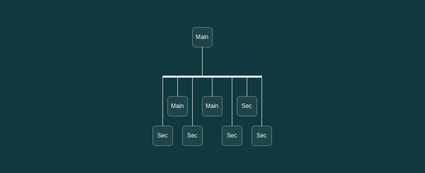 Main -- big dataline - Main and Secondaries illustration
All devices needs adresses.
Main -- big dataline - Main and Secondaries illustration
All devices needs adresses.
Protocols
UART

serial communication. add illustrations from the slides
RT connects to TX of the other board and vise versa. GND to GND aswell
 There is no clock but a fixed speed. We call this achronous. YOu set devices to a set baud speed. Ex: 9600 baud (bit/sec). 8 data bits, no parity bit. 1 stop bit.
Asynchronous
    No clock
    Rx / Tx with a fixed speed
Synchronization rules
    9600,8,n,1
        9600 baud (= bit/second)
        8 data bits
        no parity bit
        1 stop bit
Parity for 1-bit error detection (no correction)
    P = d0 ⊕ d1 ⊕ d2 ⊕ d3 ⊕ d4 ⊕ d5 ⊕ d6 ⊕ d7
    0 for even
    1 for odd
RS232 // pretty old
    UART with +/- 15 V levels
RS485
    UART with differential signals
    Full duplex (4 wires) / Half duplex (2 wires)
We hardly use RS232 and RS485 anymore.
RS485 *make some diagrams*
 Differential signals + twisted wires for lower EM
It uses ethernet cable.
Erwins Lame claim to fame: AVR’s MPCM
Multi Processor Communication Mode
8-bit address with this-is-an-address bit
Upon receiving an address, each µC checks the address
Only the addressed µC switches to regular receive
All others remain in MPCM and wait till the next address
All implemented in hardware
limited interruption on running code
limited impact on memory and program size
more like a but topology
Differential signals + twisted wires for lower EM
It uses ethernet cable.
Erwins Lame claim to fame: AVR’s MPCM
Multi Processor Communication Mode
8-bit address with this-is-an-address bit
Upon receiving an address, each µC checks the address
Only the addressed µC switches to regular receive
All others remain in MPCM and wait till the next address
All implemented in hardware
limited interruption on running code
limited impact on memory and program size
more like a but topology
SERIAL
SPI
 Uses more pins then I2C. illustrate
Advantage: More pins = higher data range. When connecting SD card it is with SPI, beacuse the data transfer is highter. TFT displays also need SPI. SPI can also send data both ways simultaniously.
Uses more pins then I2C. illustrate
Advantage: More pins = higher data range. When connecting SD card it is with SPI, beacuse the data transfer is highter. TFT displays also need SPI. SPI can also send data both ways simultaniously.
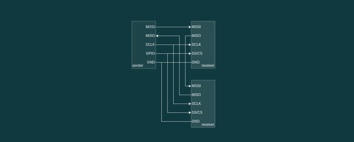
Serial Peripheral Interface Invented by Motorola
Exchange of data between main – secondary (MISO – MOSI) High data-rate Clock for data synchronization Use Chip Select (CS) to specify which receiver to talk to
Or use daisy-chaining to send all data in one stream to all receivers (same principle as NeoPixels)
illustrate
 Mode 0
CPOL 0 // chip select
MOSI rising // main to secondary
MISO falling // secondary to main
Mode 0
CPOL 0 // chip select
MOSI rising // main to secondary
MISO falling // secondary to main
Fast, so often used for flash memory SD cards displays Accelerometer in my Input Shaper Calibrator
I2C I2C is an inter-IC Communication invented by Philips.

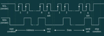 It uses a 7-bit address wich is mostly fixed:
PCA9555 // multiplexter
    0100<A2><A1><A0>R/W
    0100000x - 0100111x
But nobody is stopping you…
10-bit address also possible, if you want to go down that rabbit hole.
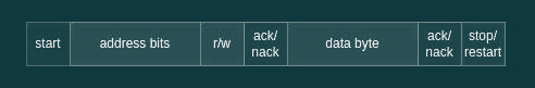
Instead of just sending bits (like UART or SPI), addressing and an operation is required. Receivers acknowledge successful reception. Sender in control of the bus. More elaborate protocols are possible.
https://learn.adafruit.com/working-with-i2c-devices
https://www.analog.com/en/analog-dialogue/articles/i2c-communication-protocol-understanding-i2c-primer-pmbus-and-smbus.html
Bus pullups Good practice to fix bus levels to ensure a valid signals Best value depends on speed Rule of thumb: SPI: 10kΩ pull-down (mode 0) I2C: 4k7Ω pull-up
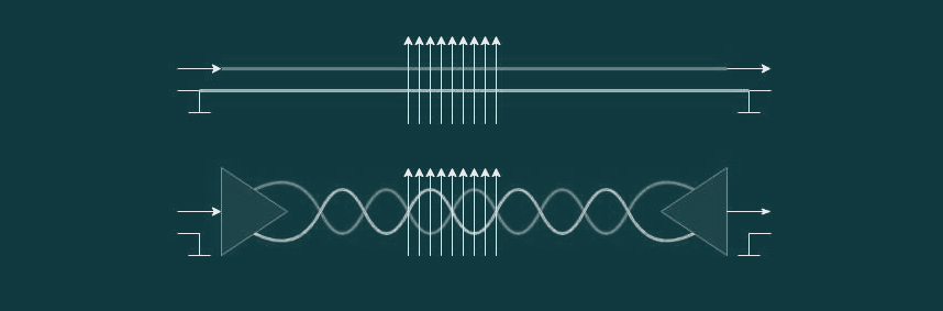
bus termination Long communication wires (many meters) or wires carrying high frequency (many kHz) signals must be terminated to prevent reflections and provide a good impedance A wire acts as a capacitor with a resistor (low-pass filter)
TCP/IP - easy to use with boards that already have wifi. Protocol used on the internet.
OSI layers
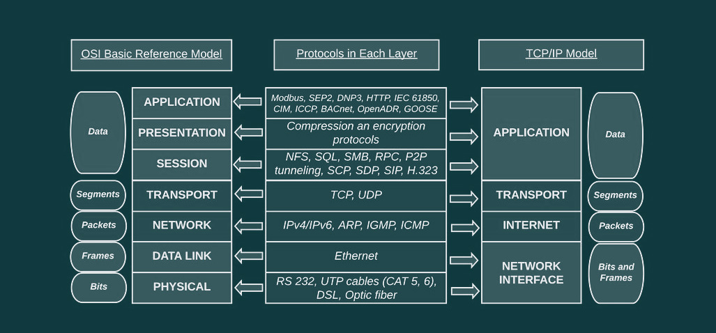
1 – physical layer - frequency we use, cables fiberoptic 2 – datalink layer - 1st signal that goes over, mac adresses, ethernet, negotiates the size of the frames to talk to each other 3 – network layer - IP-adresses, IPV4/IPV6 ect 4 – transport layer - TCP/UDP, segments, communication of if the TCPIP - protocol for important data transfer. Lets know if package is recieved. UDP is mostly used in streaming data, vid and audio transper, and VPNs. Its very fast, since it does not wait for an accnowledgement from reciever. Glitches. 5 – session layer - which protocols we are using for communication. peer to peer, HTTP ect. 6 – presentation layer - presentation of data: compressed, encryption? 7 – application layer - tells what kind of protocol it is.
TCP/IP Transmission Control Protocol / Internet Protocol Invented by DARPA for highly resilient communication - meaning: reach a goal on different routes. IETF RFC’s - no idea what this is.
IP address (routable) each device has an IP Subnet - each network has one Default gateway - each subnet has a default gateway.
Underlaying: MAC addresses (not routable)
IPv4 95.216.151.48 Network Address Translation / local these are used all over the world for local networks. 10.0.0.0/8 172.16.0.0/12 192.168.0.0/16 IPv6 // used less then IPv4 - starting to get used more now. escpecially in CHina and Africa, with many users. 2a10:3780:2:52:185:93:175:46 negatie: you can only reach websites that are configured with IPV6, not only IPV4. If it has been configured for both acess is still possible.
TCP/IP – Subnet and beyond
Subnet determines scope of local network Common subnetmask: 255.255.255.0 or /24
Calculate if destination IP is local or not
Resourses
I2C debugging guide IC2 documentation FabLab Leon Niels Notes