10: Output devices
Group assignment
This weeks group assignment is to measure the power consumption of an output device.
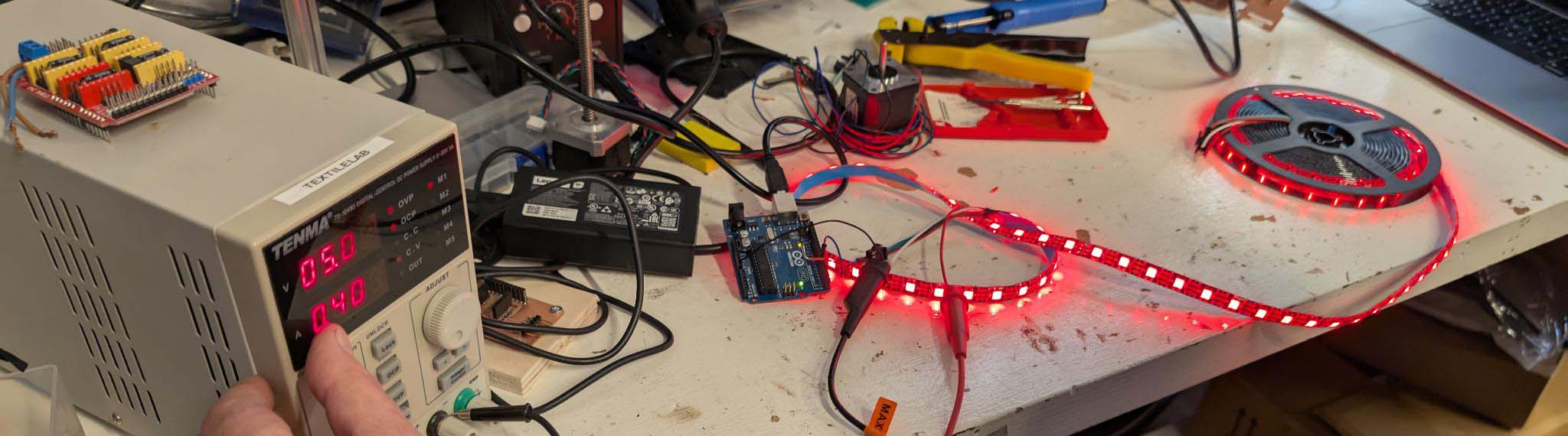
With Henk we looked at the powerconsumption of an LEDstrip. Here we could see that the more led were activated the more amerage was drawn form the powersupply. The change of colors and brightness also impacted this.
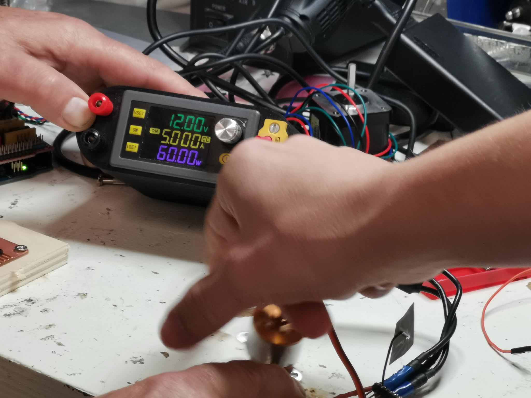
We used Sams homemade power supply to measure the power consumption of one of his brushless motors. It shows the voltage, amerage and watt consumption of the device. We hooked it up to the motor he is using for testing his drone.
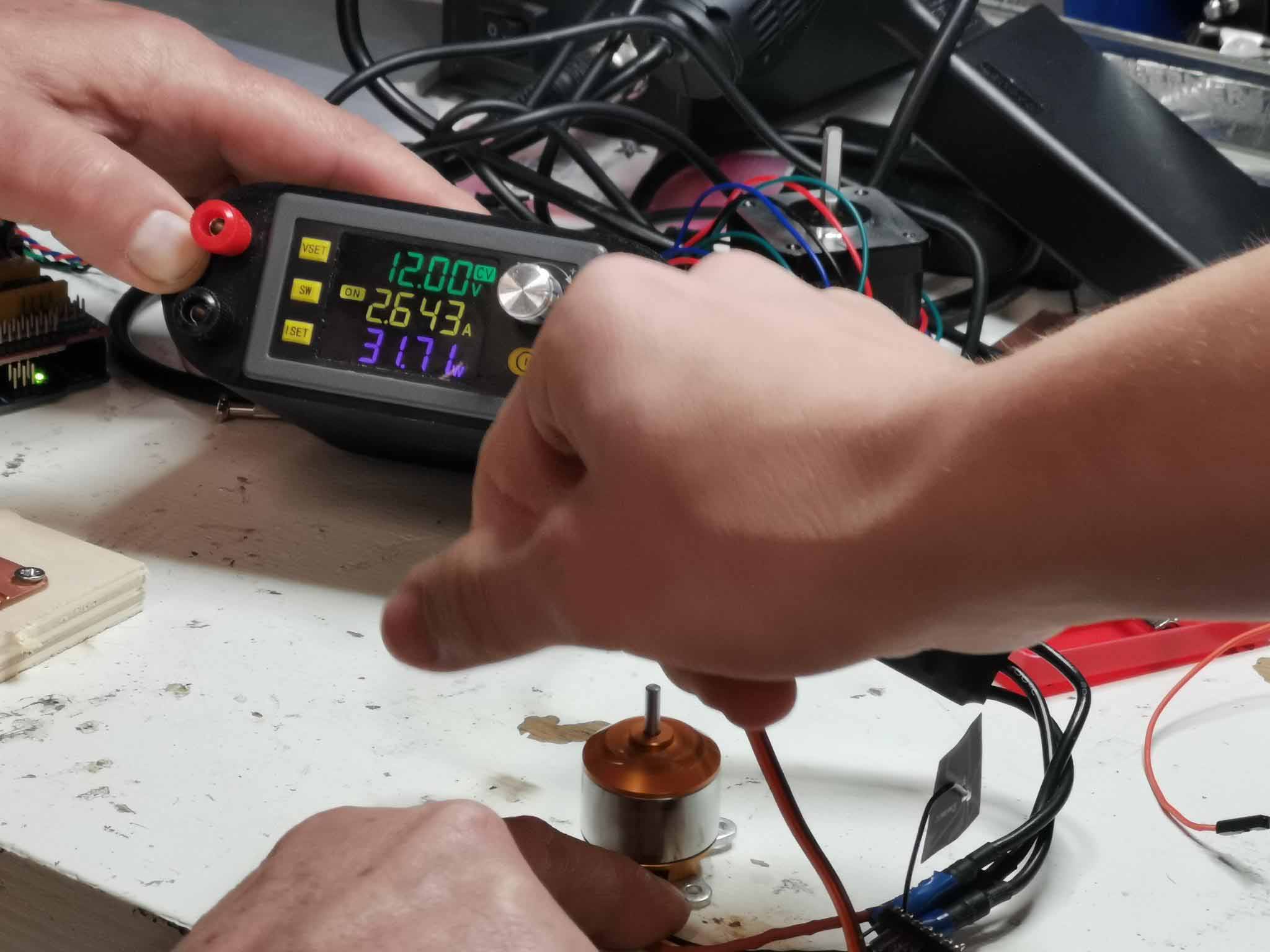
When we applied resistance to the motor by touching it it upped the amerage ar it needed to draw more power to keep its speed.
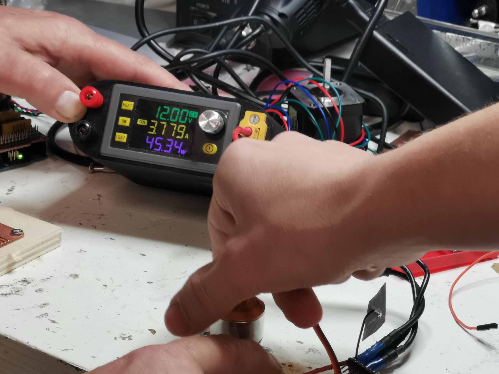
There is a shut off function on the power supply that shuts it off when it reaches 5A.
Individual assignment
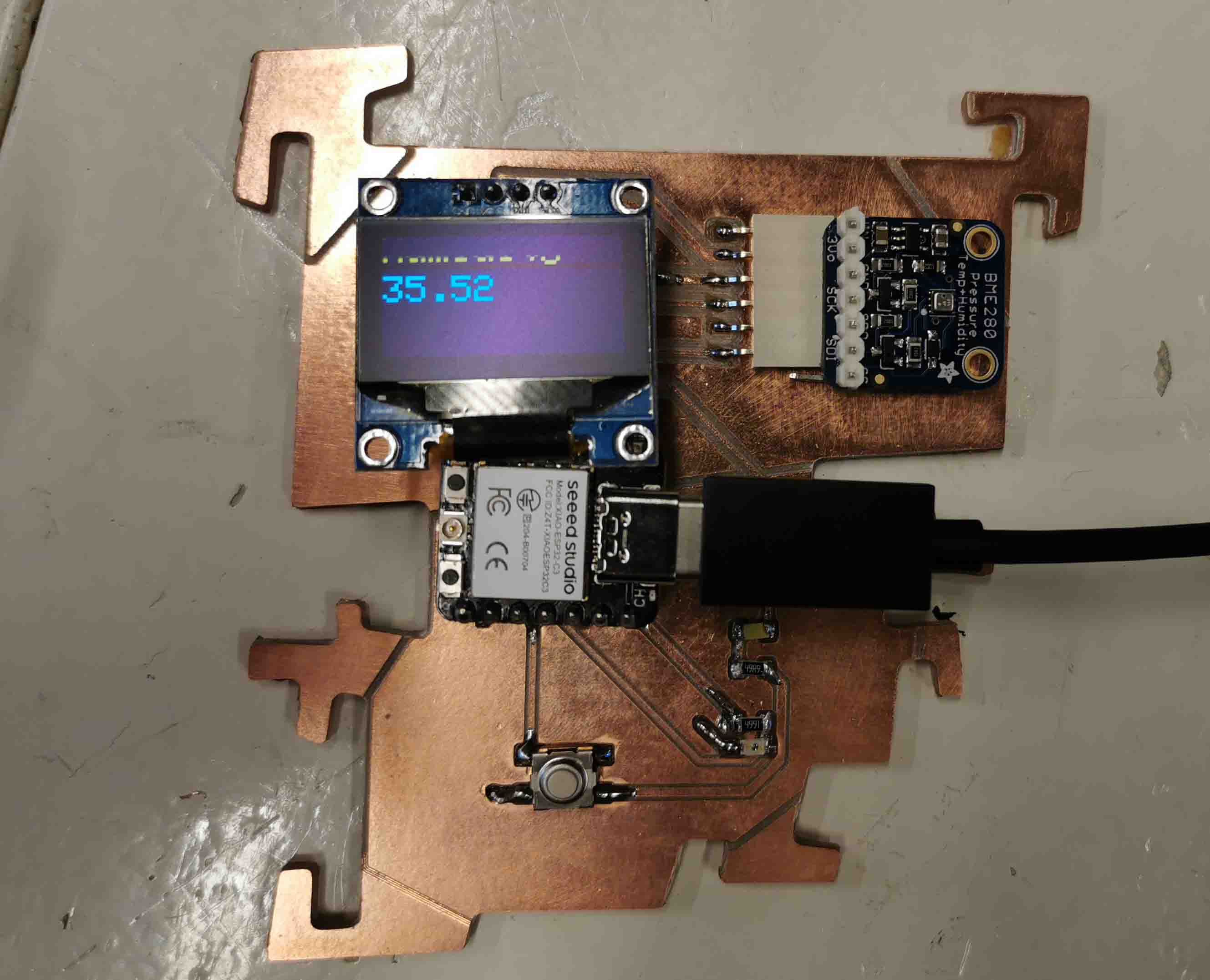
The individual assignement this week is to add an output device to a board you have designed and program it to do something. I decided to take my humidty board and program the OLED to display the humidity picked up by the BME280 sensor.
To start out I used my 2 example codes. they are both supplied by libraries in Arduino/
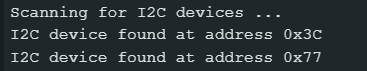
I used the wire library to search for I2C devices on my board. The scanner found 2 with the adresses 0x3c and 0x77.
- Humidity sensor: 0x3C
- OLED display: 0x77
I combined some example codes from the Adafruit_BME280 library and Adafruit_SSD1306 library to display the humidity picked up by the sensor on the OLED dispaly. It is a bit difficult to get a good picture. It says "Humidity:" at the top of the screen:
Here is the code:
/* These sensors use I2C or SPI to communicate, 2 or 4 pins are required
to interface. The device's I2C address is either 0x76 or 0x77.*/

#include <Wire.h>
#include <Adafruit_BME280.h>
#include <Adafruit_GFX.h>
#include <Adafruit_SSD1306.h>

#define SCREEN_WIDTH 128 // OLED display width, in pixels
#define SCREEN_HEIGHT 64 // OLED display height, in pixels

#define OLED_RESET     -1 // Reset pin # (or -1 if sharing Arduino reset pin)
#define SCREEN_ADDRESS 0x3C ///< See datasheet for Address; 0x3D for 128x64, 0x3C for 128x32
Adafruit_SSD1306 display(SCREEN_WIDTH, SCREEN_HEIGHT, &Wire, OLED_RESET);

#define NUMFLAKES     10 // Number of snowflakes in the animation example

#define LOGO_HEIGHT   16
#define LOGO_WIDTH    16


Adafruit_BME280 bme; // I2C


unsigned long delayTime;


void setup() {

    //Humidity setup
    Serial.begin(9600);
    while(!Serial);    // time to get serial running
    Serial.println(F("BME280 test"));

    unsigned status;
    status = bme.begin(0x77);

    Serial.println("-- Default Test --");
    delayTime = 1000;

    Serial.println();

    if(!display.begin(SSD1306_SWITCHCAPVCC, SCREEN_ADDRESS)) {
        Serial.println(F("SSD1306 allocation failed"));
        for(;;); // Don't proceed, loop forever
    }

    display.display();
    delay(2000); // Pause for 2 seconds

    // Clear the buffer
    display.clearDisplay();

    // Draw a single pixel in white
    display.drawPixel(10, 10, SSD1306_WHITE);

}

void loop() {


    printValues();
    delay(delayTime);

    display.clearDisplay();
    display.setTextSize(2);
    display.setTextColor(WHITE); // needs to be here
    display.setCursor(0,0);
    display.println("Humidity:");
    display.setTextSize(3);
    display.setCursor(20,35);
    display.println(bme.readHumidity());
    display.display();
    delay(2000);


}

void printValues() {

    Serial.print("Humidity = ");
    Serial.print(bme.readHumidity());
    Serial.println(" %");

    Serial.println();
}
Work for personal project
This week I will be working on building a board for an ultrasonic atomiser for my humidifier. I bought some mistmodules from TinyTronics a while back. I then turned then surpassed the button and used relays to turn them off and on. After 5 minutes they always stopped working. I then soldered across the button. Then the module would click loudly every time the atomizer turned off or on. My goal is to have a module that can quietly activate different atomizers and be fabricated in the FabLab.
Understanding the module:
In order to understand what I am trying to do and what has been done before. If anyone is reading this and attempting to do the same I've listed here links to a bunch of different sources on this:
Example 1: schimatic from electroschematics
Example 2: Another schematic from electroschematics
Example 3: instructables: Make your own Super Simple Ultrasoni Mist Maker
Example 4: instructables: DIY mistfog maker using IC 555
PWM control ESP32 Built-in ADC
Ultrasonic Atomizer board
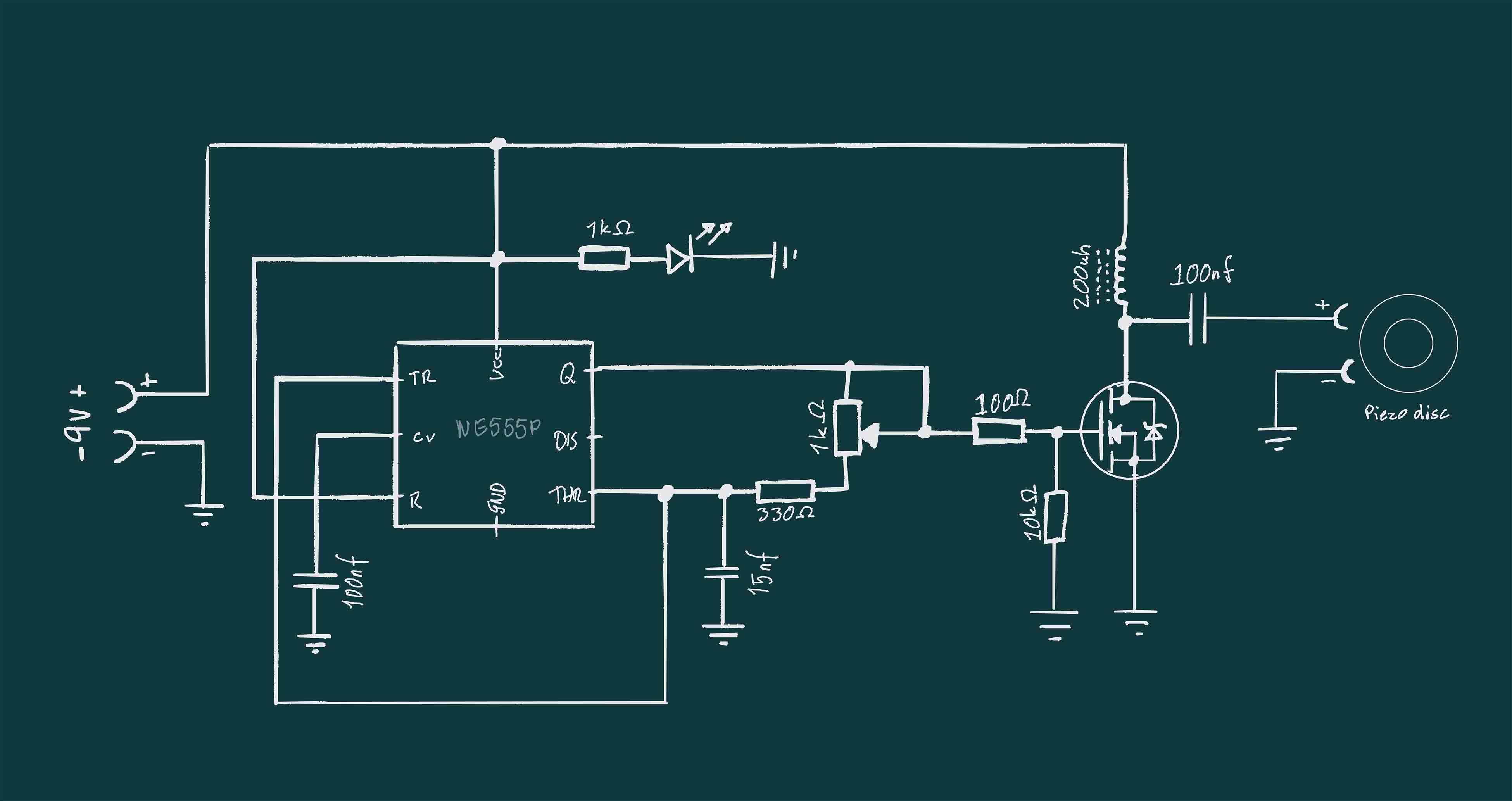
After scouring the internet for a long time and watching every video and reading a bunch of posts from people attempting to do the same as be I decided decided to use this video from Creative technos as my starting point. He has a drive where both schimatics and gerber files can be found. And I see he has an updated schimatic. This runs on 9V instead of the original 15V.
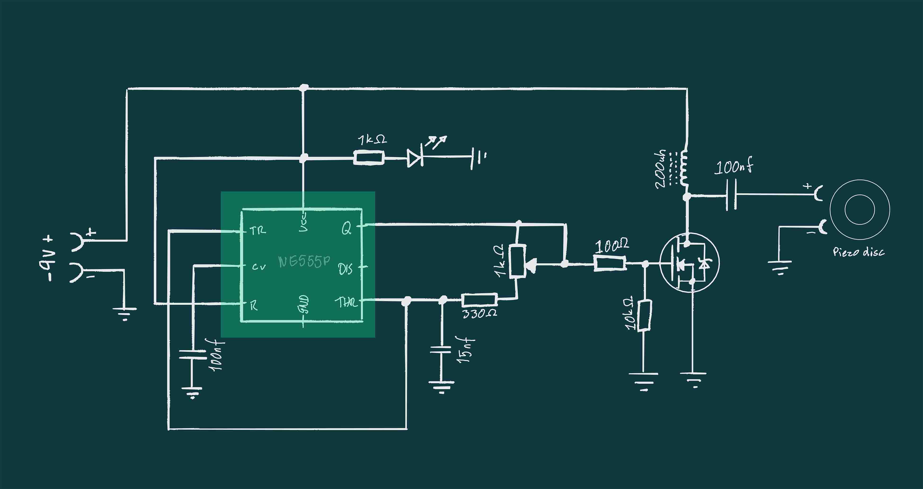
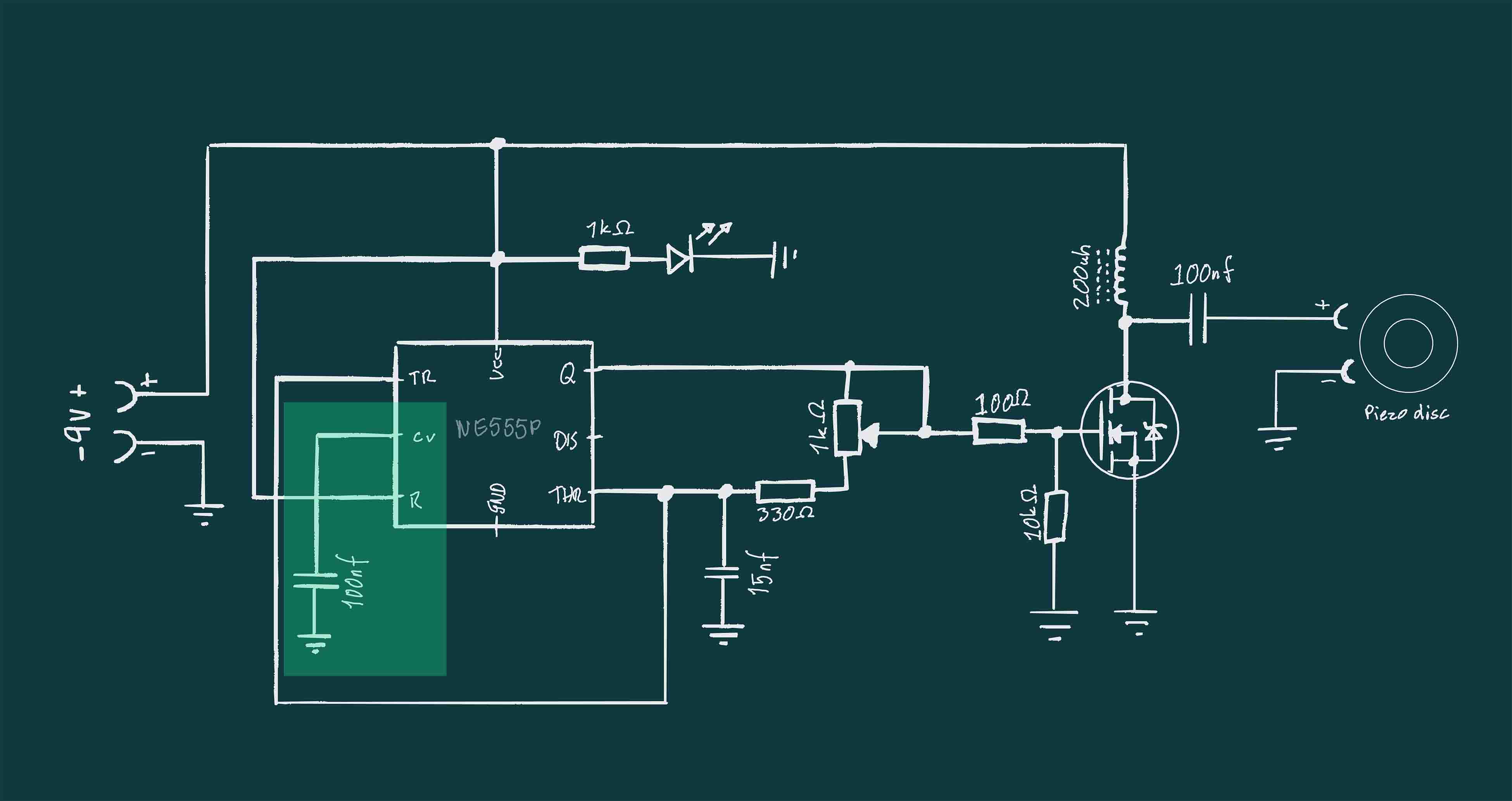
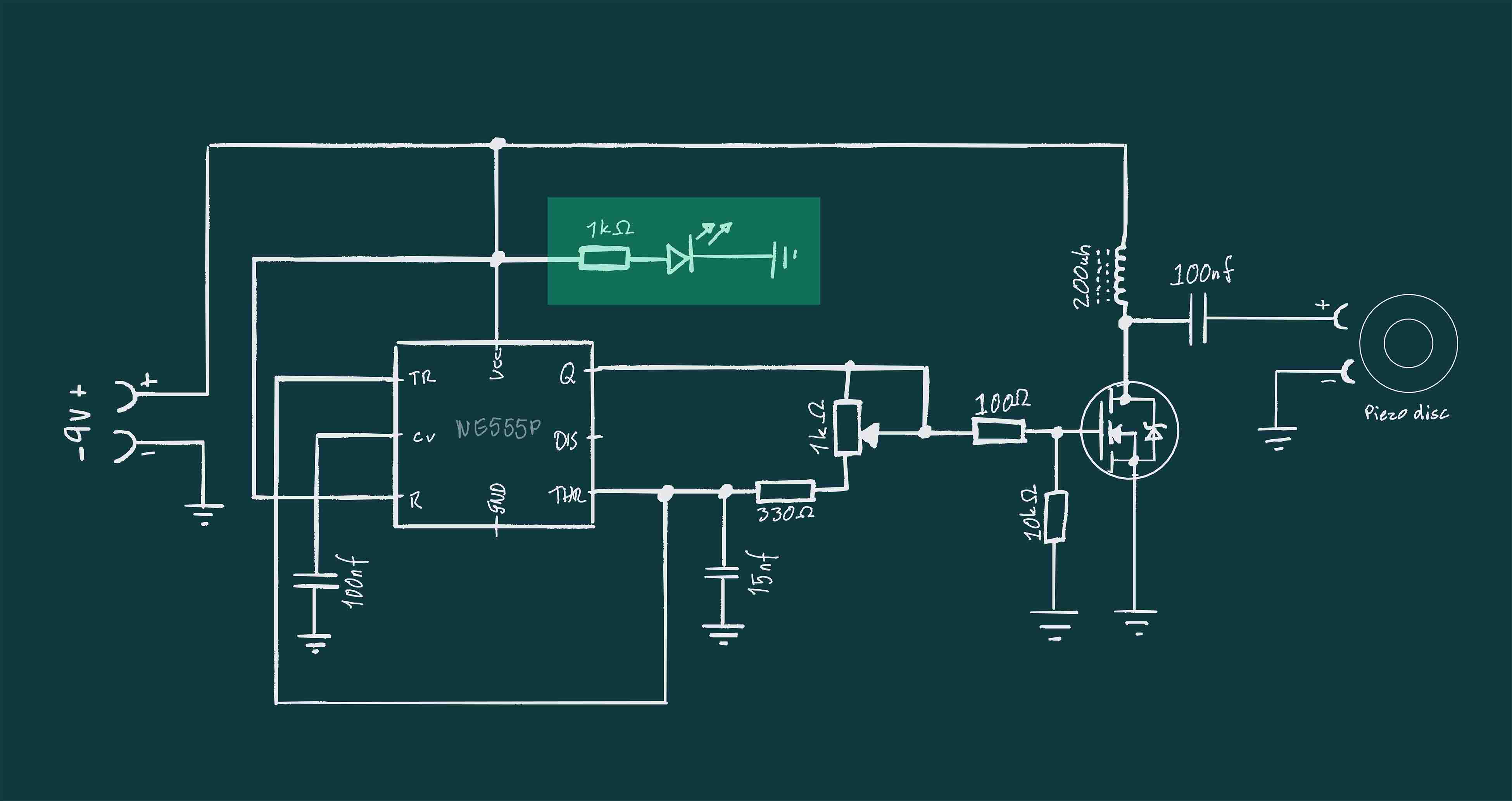
I have drawn Creative Technos schimatic out in order to understand it better for myself.
Parts
One of my big problems with trying to understand what other people were doing is that I am very new to reading schematics and get lost in what the different parts are, how they work and what they are doing. I'll therefore try to make an explanation of this, but keep in mind that I still don't really know what I am doing.
Here is a list of all the components:
IRFZ44 Mosfet: Datasheet
NE555P: Datasheet, DigiKey, Great Scott explanation video
1k potentiometer: Part
220 uH ferrite inductor: Part
Capacitors: 2x 100nf, 15nf
Piezo disk
Resistors: 300 ohm, 1K ohm, 100 ohm and 10k ohm
NE555P precition timer
NE555P: Datasheet, DigiKey Great Scott explanation video
From datasheet:
The Nx555 and Sx555 devices are precision timing circuits capable of producing accurate time delays or oscillation. In time-delay or monostable operating modes, the timed interval is controlled by a single external resistor and capacitor network.
Trigger level: ca 1/3 of supply Voltage Threshold level: ca 2/3 of supply Voltage
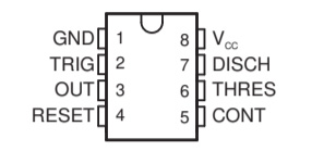
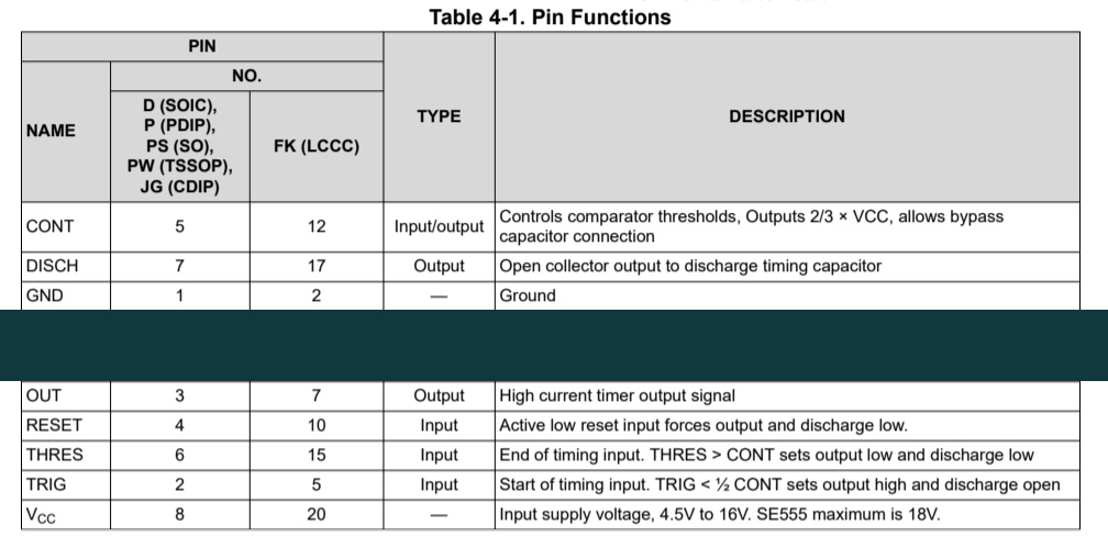
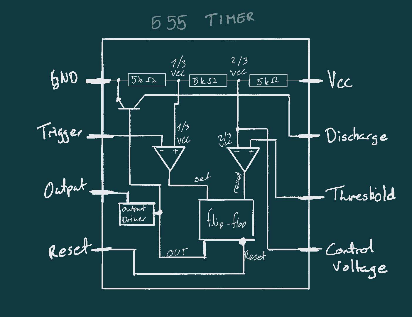
Illustration copied from Great Scotts explanation video og 555 timers.
inductor

Inductors slows down current surges or spikes by temporarily storing energy in an electro-magnetic field and then releasing it back into the circuit.
THere are 2 kinds of inductors: air (or ceramic) inductors and ferrite (or iron) inductors.
In this project the inductor is used to create a tuned oscillator of LC "tank" circuit. Using an inductor and a capacitor.
Timed circuits are used for transmitting or recieving radio or microwave frequency signals. Inductors can be combined with capacitors to create LC circuits such as oscillators.
How does the inductor work and what is it doing in my project?
When an conductor and a capacitor is placed in series they create something called an LRC oscillator.
The capacitor stores energy in its e-field and then inductor stores energy in its b-field. To greate an oscillating signal the energy gets passed back and forth between the 2 fields.
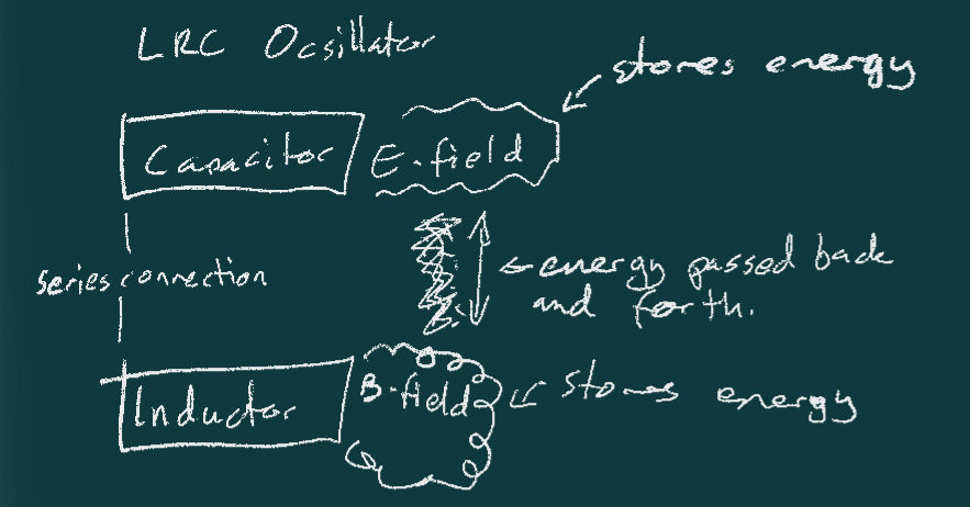
Here is an explanaition video for capacitors. info about ocillation types by Great Scot
IRFZ44 Mosfet
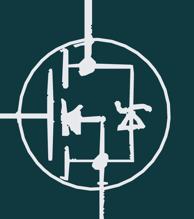
Im using this instead: mosfet from the fablab
From what I can understand the mosfet is what is used to make the current go back and forth between the inductor and the capacitor. I could be wrong, but I believe the mosfet is controlled by the signal sent out from the 555 IC and this change alternates the current causing the LC ocsillation.
Potentiometer
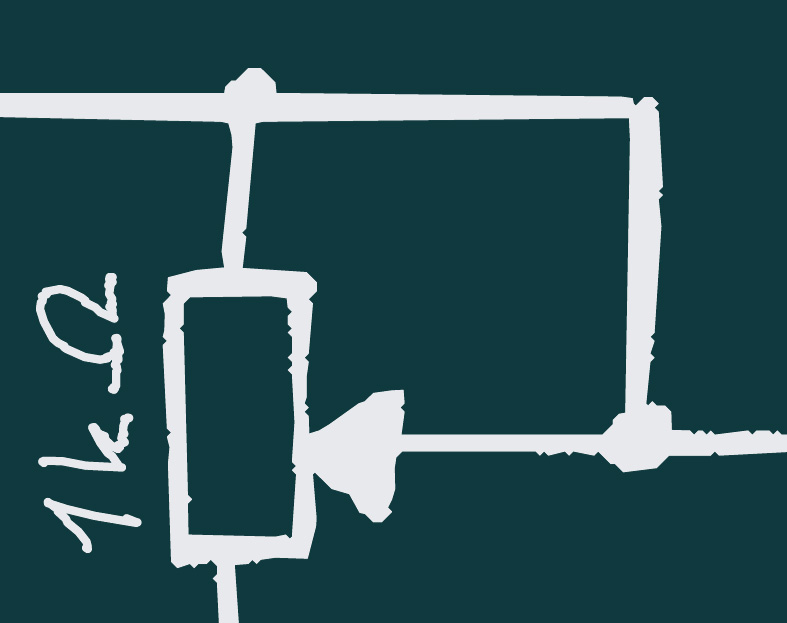
The potentiometer in the circuit seems to be used to set the right oscillating frequency. A way to fintune the output.
Control Voltage
The control voltage is connected to the ground through a capacitor.
LED
The LED is there to indicate that the circuit is on. When I tested my modules the LED worked, despite the boards being faulty.
Power source
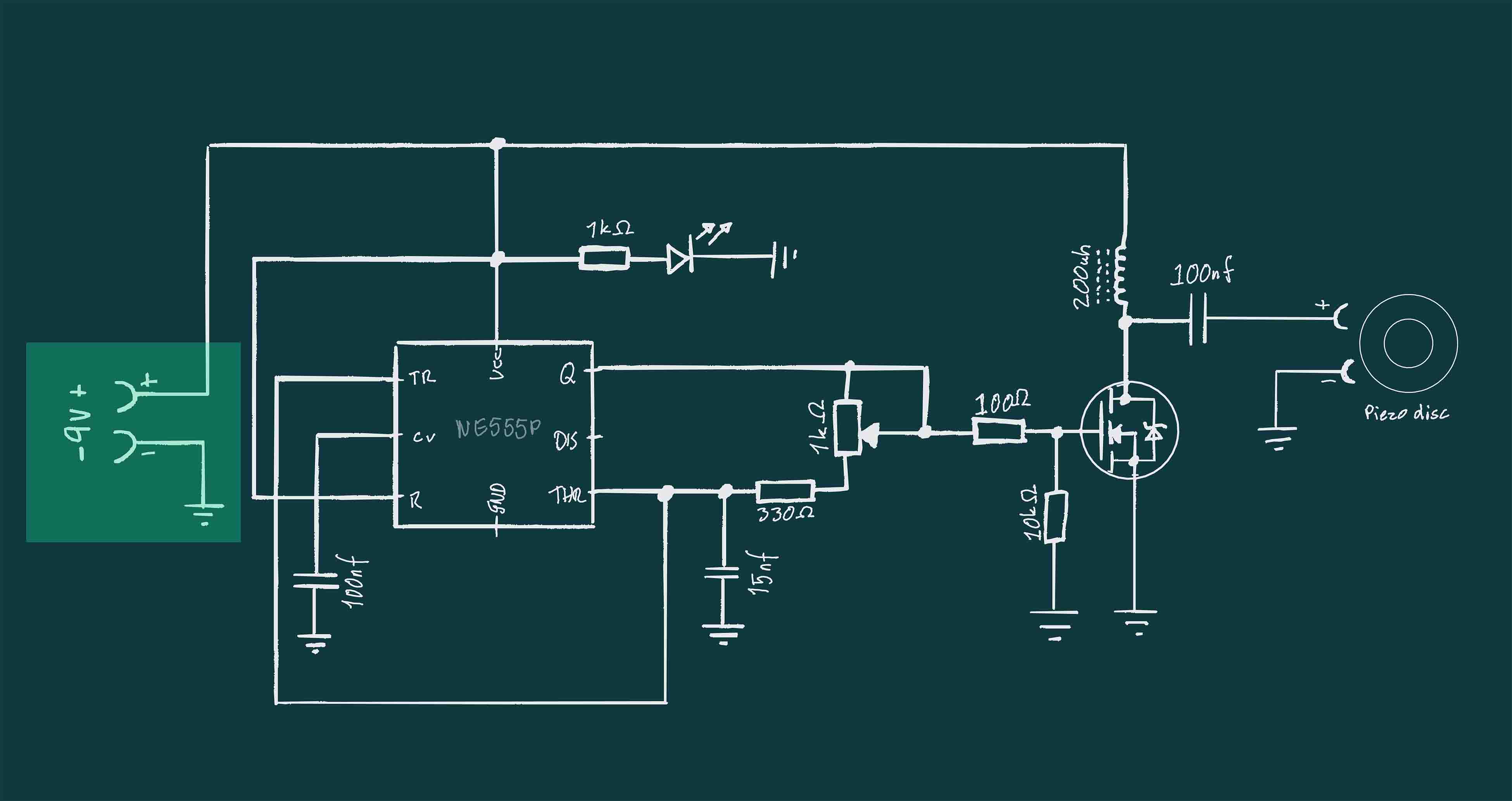
There is a 9V power supply connected to this module.
Test 1
I milled a board based on the schematic from Creative technos. I replaced the 220uH ferrite inductor with 2x ceramic inductors. This became a very smokey board when I plugged it in. The ceramic inductors could not handle the input.
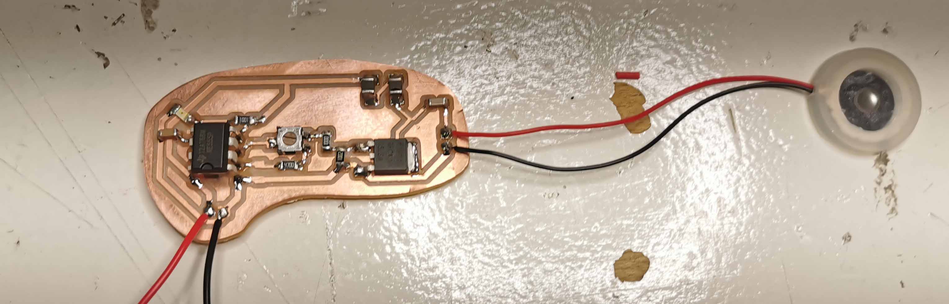
Test 2
For the next test I went and got a 220uH ferrite inductor. It was not easy to find. We did not have one in the lab and Radio Twenthe in the Hague also did not have one. In the weekend I went to Alkmaar and stopped by Smorenberg and they had 1!
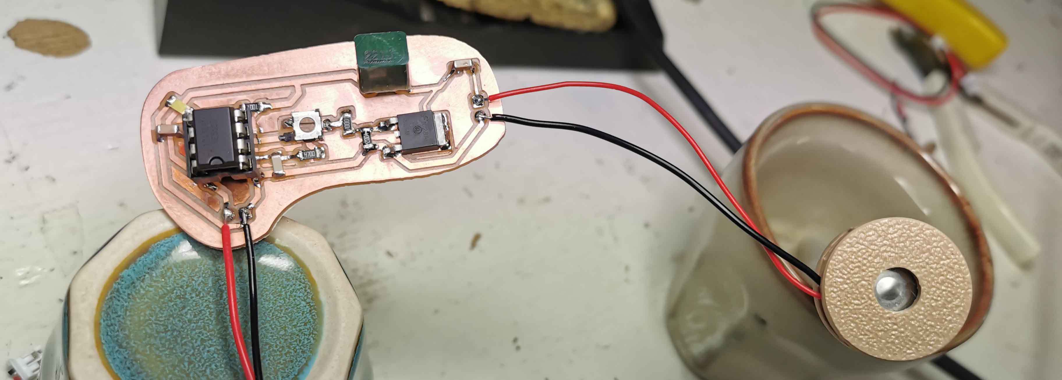
When I milled my new board I realised that I had put on the potentiometer the wrong way in my first board. So I changed the positioning and wiering and tried again.
This board was less smokey! But it was still frying. The Led turned on, but the piezo did nothing. After a bit the inductor started smoking and I turned off the power supply.
Resourses
Intro to Output devices presentation given by Henk and slides made by Erwin.
Reflection
This week has been alright, if only a bit disapointing. I really really wanted to learn how to create a module for the ultrasonic atomizers for my humidifier, so I am a bit bummed that it did not work out. On the other hand I now understand more about how it could potentially work. And I think it might not be worth the effort to do that right now. I can better use the already working modules and control them with a microcontroller. It's time to get a working prototype going. On the plus side my "wall board", as I like to call it is now displaying the humidity on the display. Meaning that I can easily go into networking week and start connecting this board through ESP NOW to the one that will control the mist makers and the touch board from last week.